captain america
-
Posts
3563 -
Joined
-
Last visited
Content Type
Profiles
Forums
Events
Gallery
Everything posted by captain america
-
Hi Jason. I'm still waiting on the canopies. They're being done now from what I can gather... Just waiting for them to come back. I'll post when I get an update.
-
This is damn peculiar: I'm getting the same problem. When I uploaded the images originally, I was on my PC. Now I'm on my Mac and while the images look OK online, whether I download them back from MW or open the ones I transferred from my PC, they have that "negative" look to them. Must be something that didn't convert over properly somehow
-
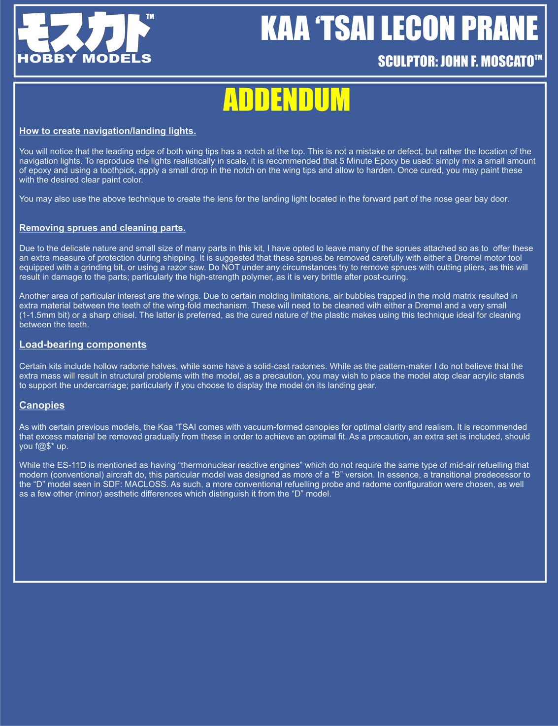
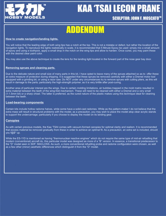
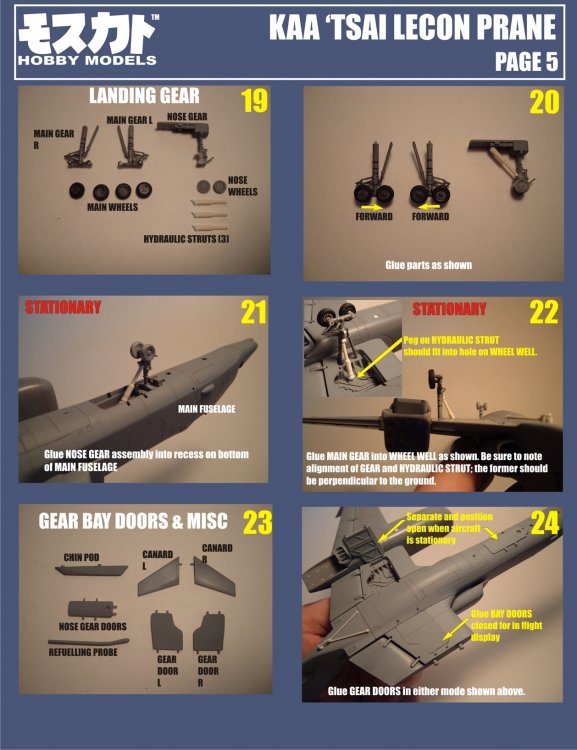
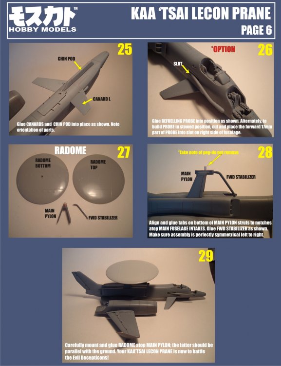
Oh, and here's the addendum page. Just a few helpful hints and explanations; those who requested email versions should have this already.
-
Hi Carl. PM me with your addy and I'll shoot those off to you. It might very well be something related to "work safety" that blocks images from certain sites. I shall adapt and overcome
-
They're all jpeg images. If you can't read them, LMK what format works better for you and I'll e-mail.
-
Hi guys! Here they are, ready for downloading. I'll probably also include a little addendum later on with tips & hints.

-
Hi bullet. From what little I know, I think it's been pretty quiet on the Macross F kit front for some time. A VF-171 would be awesome, but knowing Bandai, they likely won't touch it.
-
I can't believe I missed this thread! Man, I gotta stop working so hard Looks like it's progressing quite well so far, and I humbly apologize once again for my super ginormous pour stubs. I can't wait to see this baby built
-
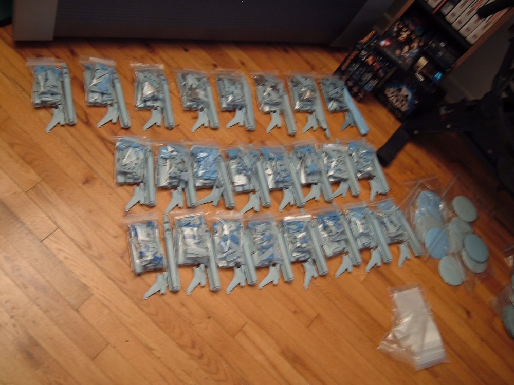
I hear ya! I have my resin straight-up! Quick little update: Kits are being bagged, then bubble wrapped & boxed as we speak; vac forming masters for the canopies are done and on their way to be produced. Will start the destructions on Monday, and should have them finished and posted by Thursday next week. 11 slots still open... Oh, and happy belated CANADA day to all the Canuckians, and a happy preemptive Independence day to everyone south of the border!!
-
Hi Kei. Awesome dio, it really has presence! Musta been a bear to open up those fuselage panels, but it was worth it; keep up the good work
-
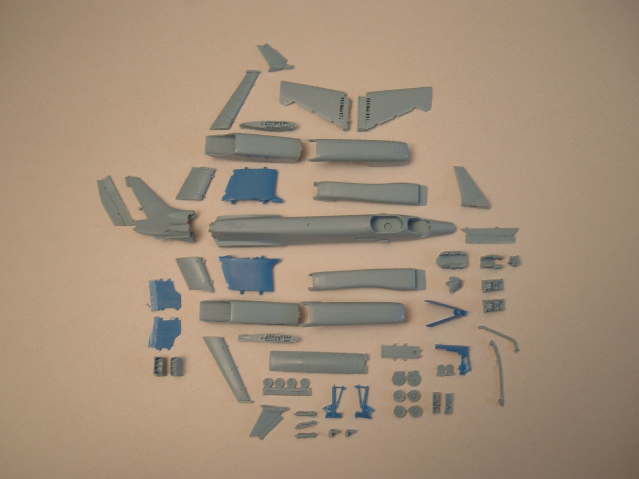
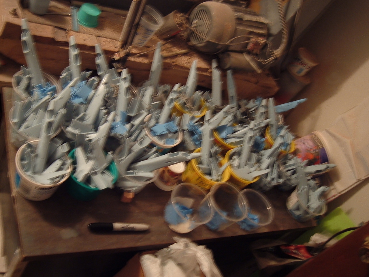
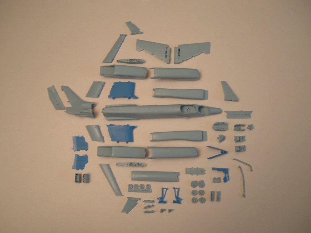
Tactical blue Quick update! Casting is going great; I've got 25 kits ready thus far, and have already re-poured a couple of molds, which is why in the exploded pic, there is no radar dish. Some of these are cast in 2 pieces (hollow) and the later versions will be 1 piece and solid. I don't foresee the extra weight being a problem, otherwise I would've just kept it hollow. Please forgive the shaky studio pic; for whatever reason, I just couldn't get my camera to cooperate. Also, I'm still waiting on the epoxy for the canopy bucks, so just another delay in the food chain, but nothing terribly unexpected. P.S: the deeper blue parts are the high-strength polymer--the one you have to bake in the oven.

-
Nope, purple is out, tan is in I figured that I'd kept the purple for the first 5 years, and figured that after that milestone, we'd be due for a change. No more grey resin either
-
Not flesh, porymer lesin
-
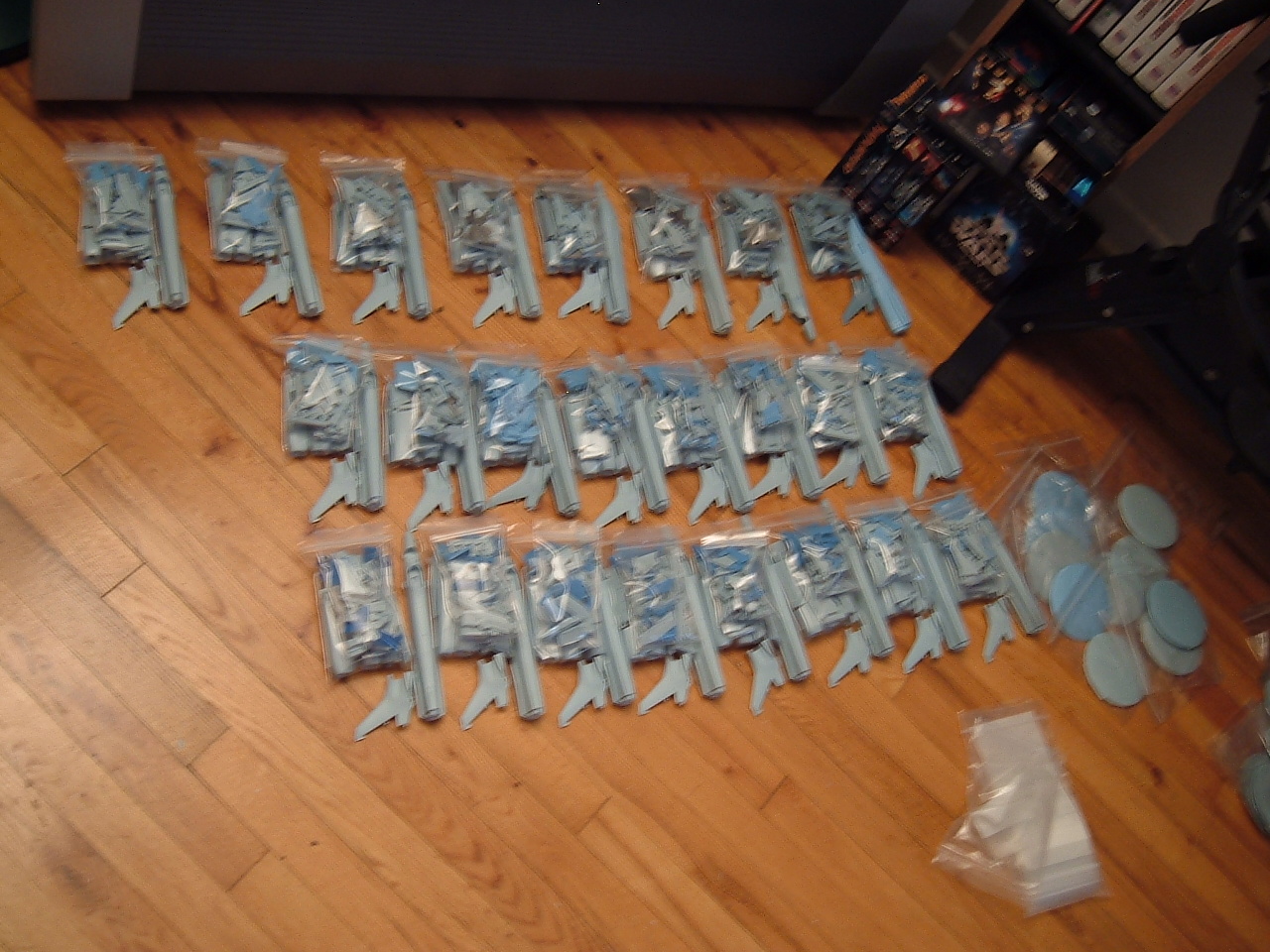
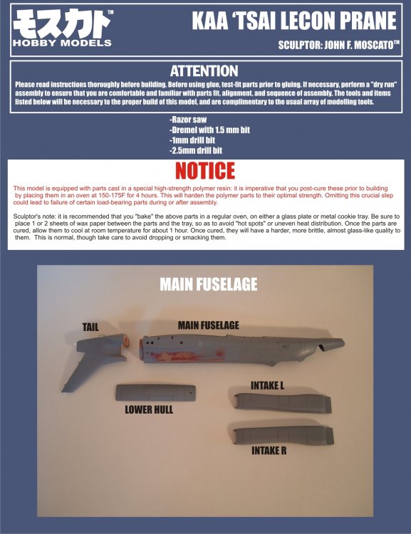
Hi everyone! Ok, as per my previous message, today kicks-off payment time for the Kaa-'Tsai, so here's the breakdown. -Each kit: $185.00 Shipping for North America: -1 kit: $16.00 -2-3 kits: $25.00 International shipping: $35.00 per kit Payments are to be accepted through Paypal, and as before, please add 4% to the total ( kit(s)+shipping ) For those of you who are new to dealing with me, you can just send me a PM with your full name & address, and I'll give you the necessary Paypal info. Important notice: I already have about 12 kits cast, but there will be an undetermined delay for the canopies, so I thank you in advance for not ripping my head off (' ) That having been said, orders will be processed on a first-paid basis, and as always, I remain at your disposal if you have any questions. I'll also be posting a pic of the overall parts breakdown early next week. I think I lost count at 64...
-
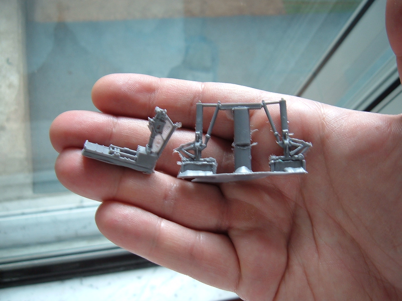
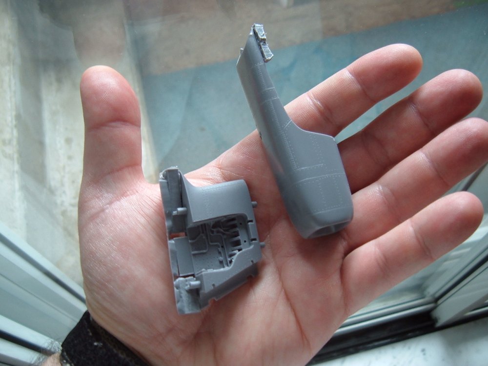
...And after lots of coaxing, praying and troubleshooting, I'm happy to say that the most delicate and pivotal parts of the kit have been cast, and the results are just excellent! You may not be able to tell, but the landing gear has 1mm brass rod going through the main shaft of each strut, and is likely strong enough to support 4 times the current model's weight. Anyway, I will have at least one fully cast model by Friday and will be able to calculate the proper shipping weight of the kits. Stay tuned

-
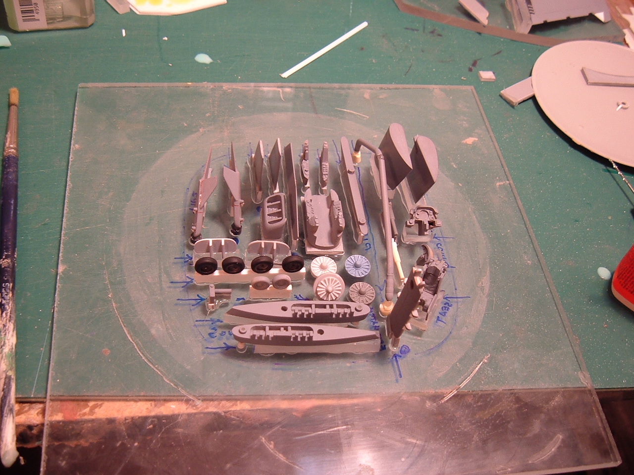
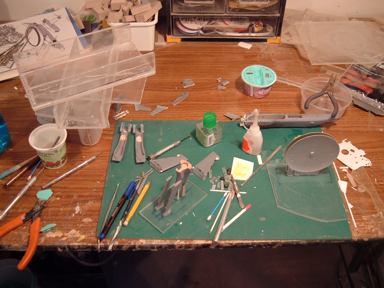
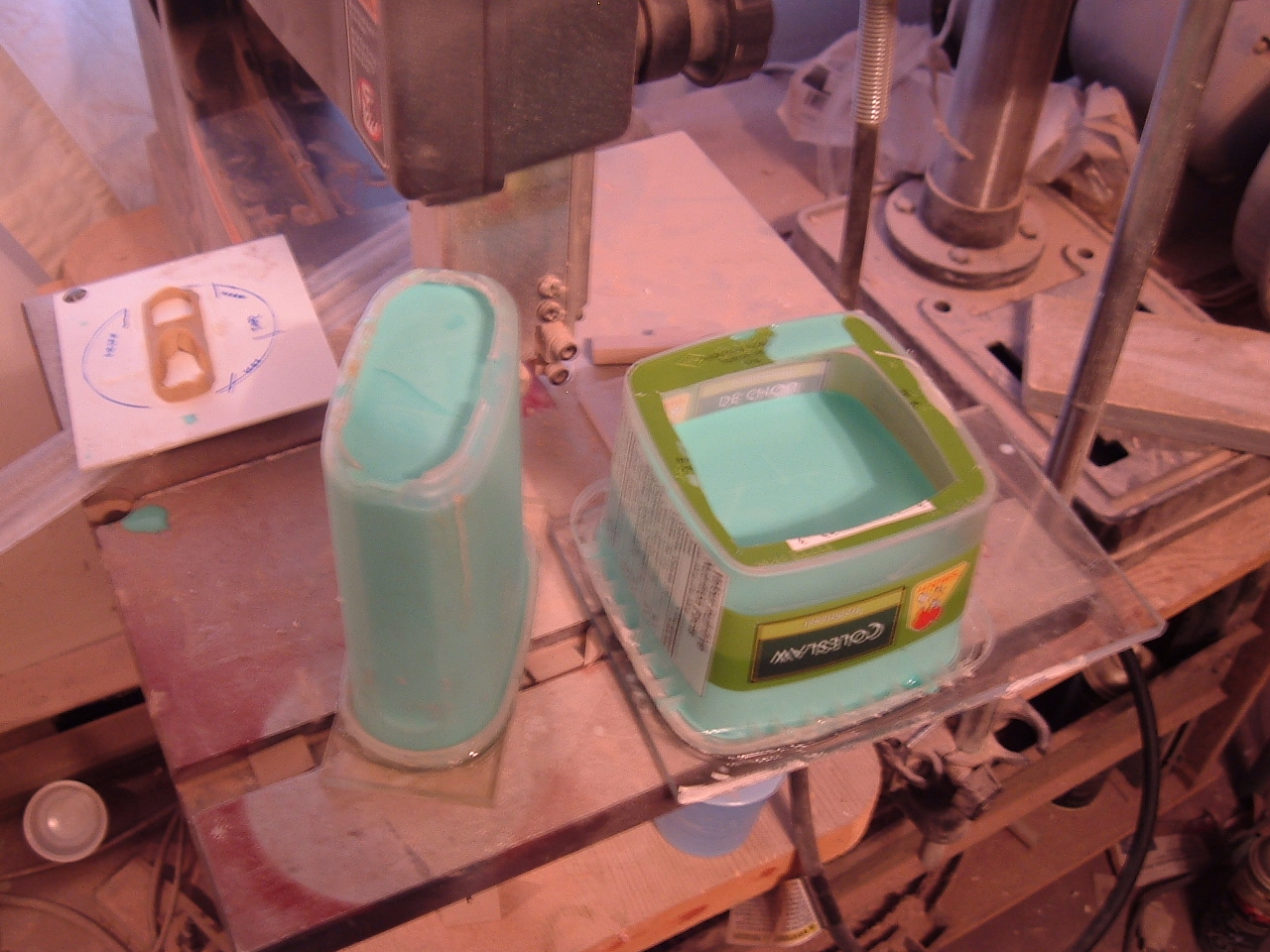
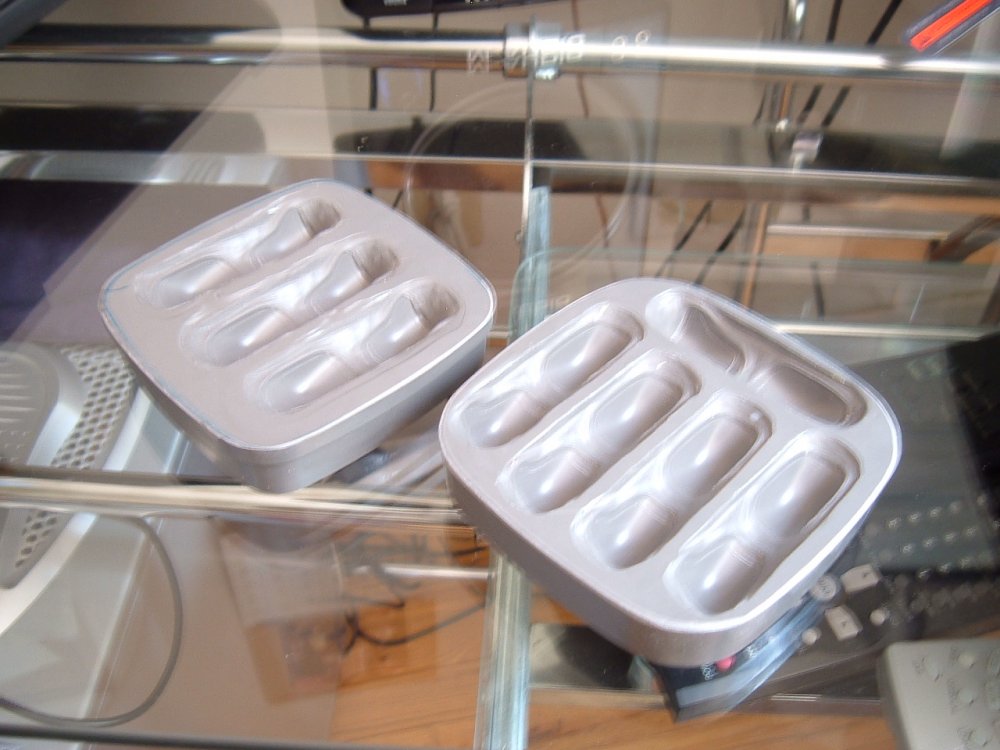
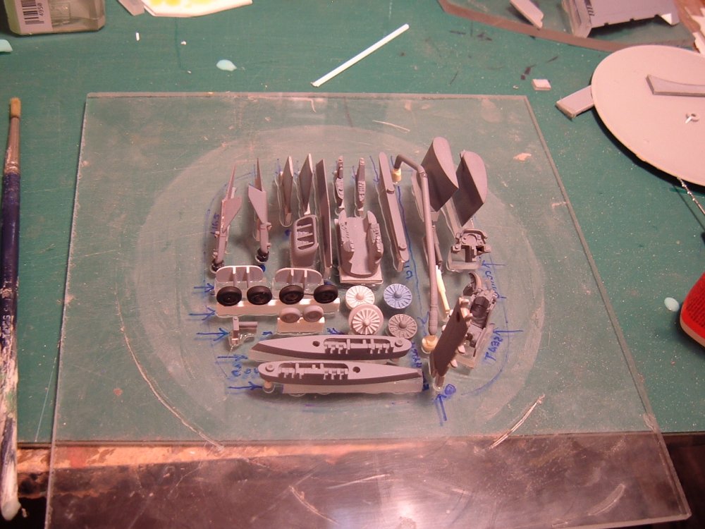
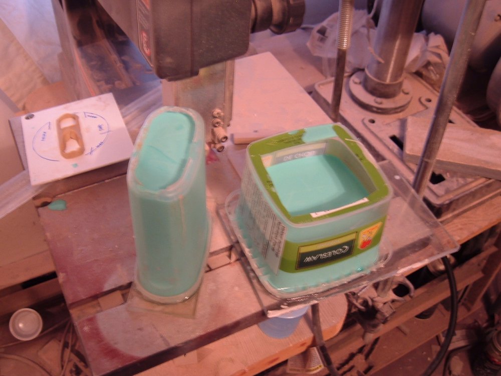
Hi everyone! Forgive me for being a little tardy in my updating; I had some molding problems that forced me to work all weekend, so the updating was put aside. Anyway, now that that crisis is taken care of, I thought I'd post these pics of my mold prep shenannigans! Pic 1: here are a whole slew of teeny, tiny parts that have been glued into place. The mold box will fit around the parts and then some minty green goop (rubber) will be poured over them to make the mold. Pic 2: various other parts are also in line to be molded. Mold prep is actually a very long and delicate procedure, especially when you have many different parts in one mold, since you can end up ruining days of work if it doesn't come out just right. Pic 3: remember that green goop I was telling you about? The rubber takes about 24 hours to harden sufficiently to be removed; very problematic if you encounter a "mold malfunction" cos you can't just clean the liquid rubber off, you have to wait a whole day or risk making even more of a mess. There are a few parts that had me worried, like the landing gear and wheel wells because of all the impossibly-thin pieces.

-
Hi Petar. I'm thinking that I'll start accepting payments around the 18th; once I've actually gotten some castings and worked-out the shipping. As always, I want to make sure that the castings are of acceptable quality before I accept any payments.
-
Yup, no change in price. I will be able to get some castings as early as next week; the only real delay will be the canopies, since I'll be farming those out.
-
Where are my f#@%*(#%^$%^ wings???
-
I never thought I'd say this, but I would have to agree. Then again, a wife-beater shirt and jeans would be better than that God-awful glorified halloween costume reject in the promo pics. The Captain votes Epic Fail!
-
I think the best word to describe the plane is "adequate." I provide the raw basics for the modeler to unlock its potential with their talent. There aren't any fixed commitments to the kit as yet, since I won't start collecting $$ for at least a week or 2, so feel free to climb aboard; still room left.
-
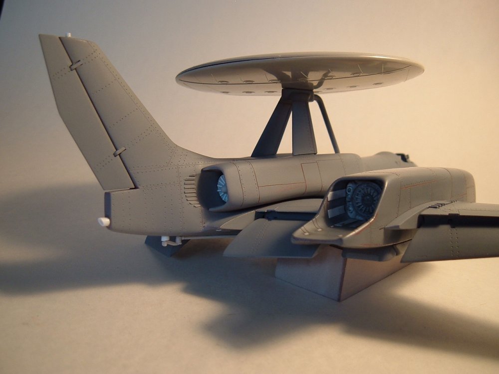
Hi Carl. In my head, I never saw the black circle on the dish as a panel demarcation. It's actually REALLY easy to do with paint or decal though; just run a compass cutter over either some Frisket film if you prefer paint, or a sheet of black decal and the job is done. 3 minutes tops if you're slow. I wouldn't recommend doing a scribed line over the top due to the layout of the raised antenna pattern, but that's just me.
-
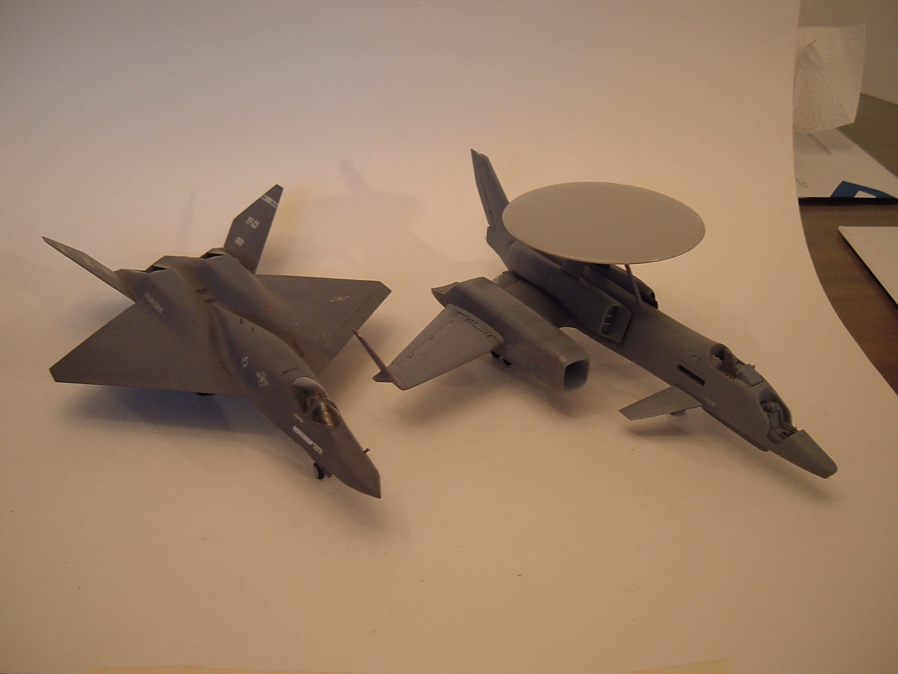
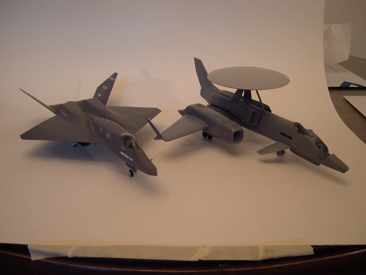
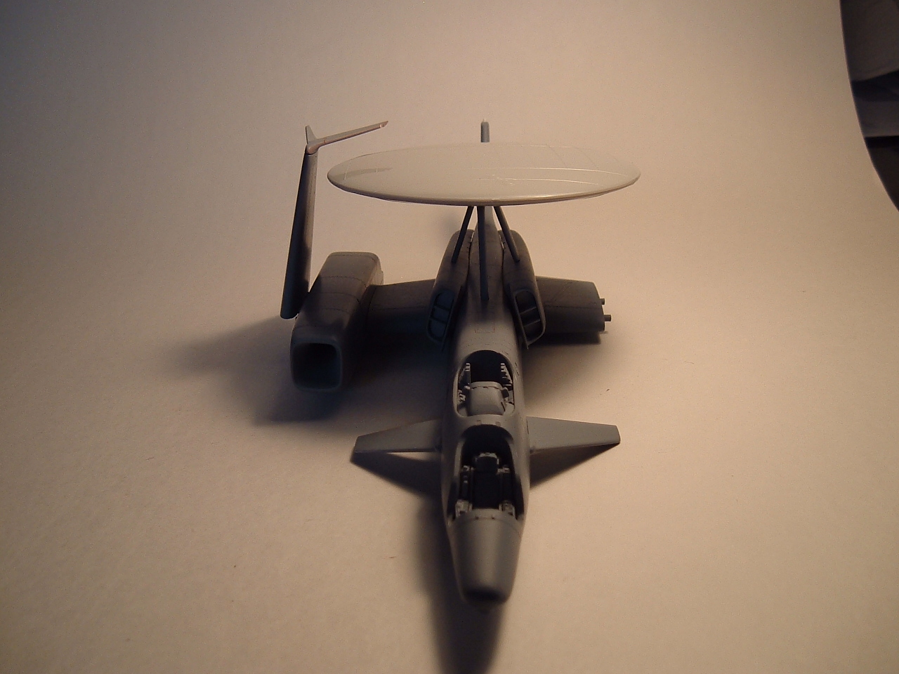
Oh, and remember back when I promised comparative pics with a YF-23? Here they are.
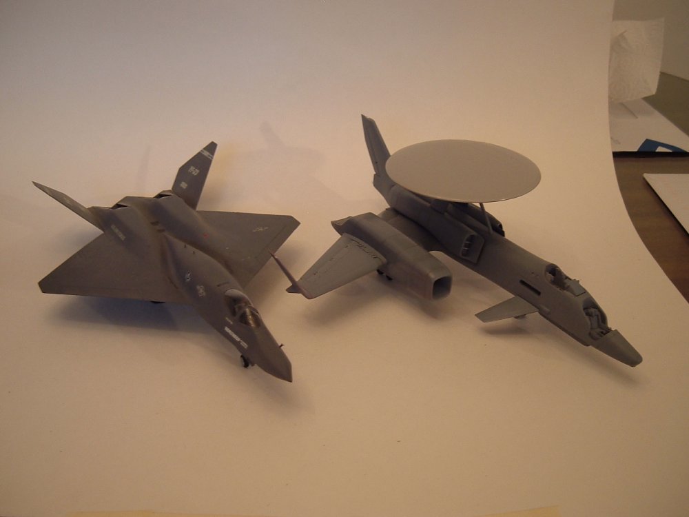

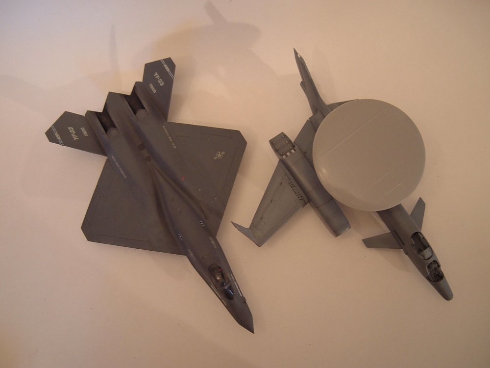
-
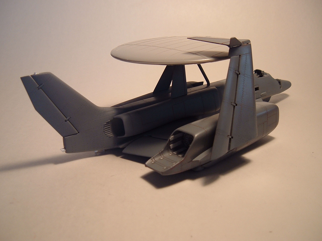
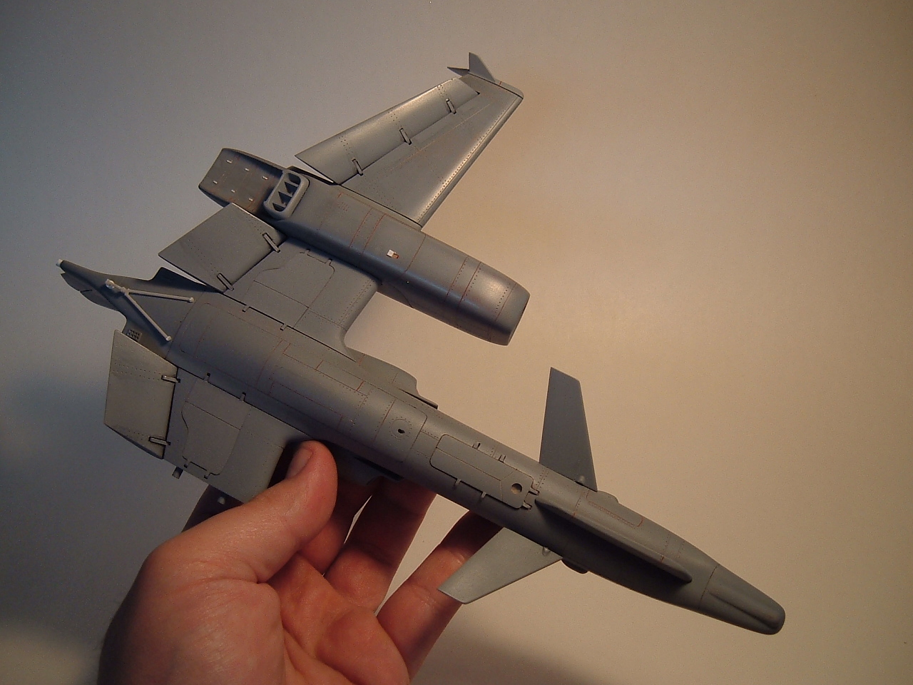
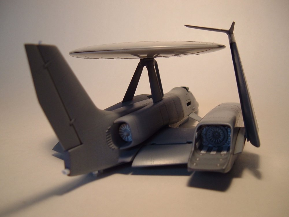
The sto-wing option. As you can see, the wings fold up into a neat little package I'll wait until parts are cast to take more landing gear shots, since the fact that I don't have a second outboard engine screws up the balance and I don't want to take the chance and damage the gear. Naturally, parts are now on their way to mold prep, but sufficed to say, this turned out to be a much cooler project than even I had hoped.


-
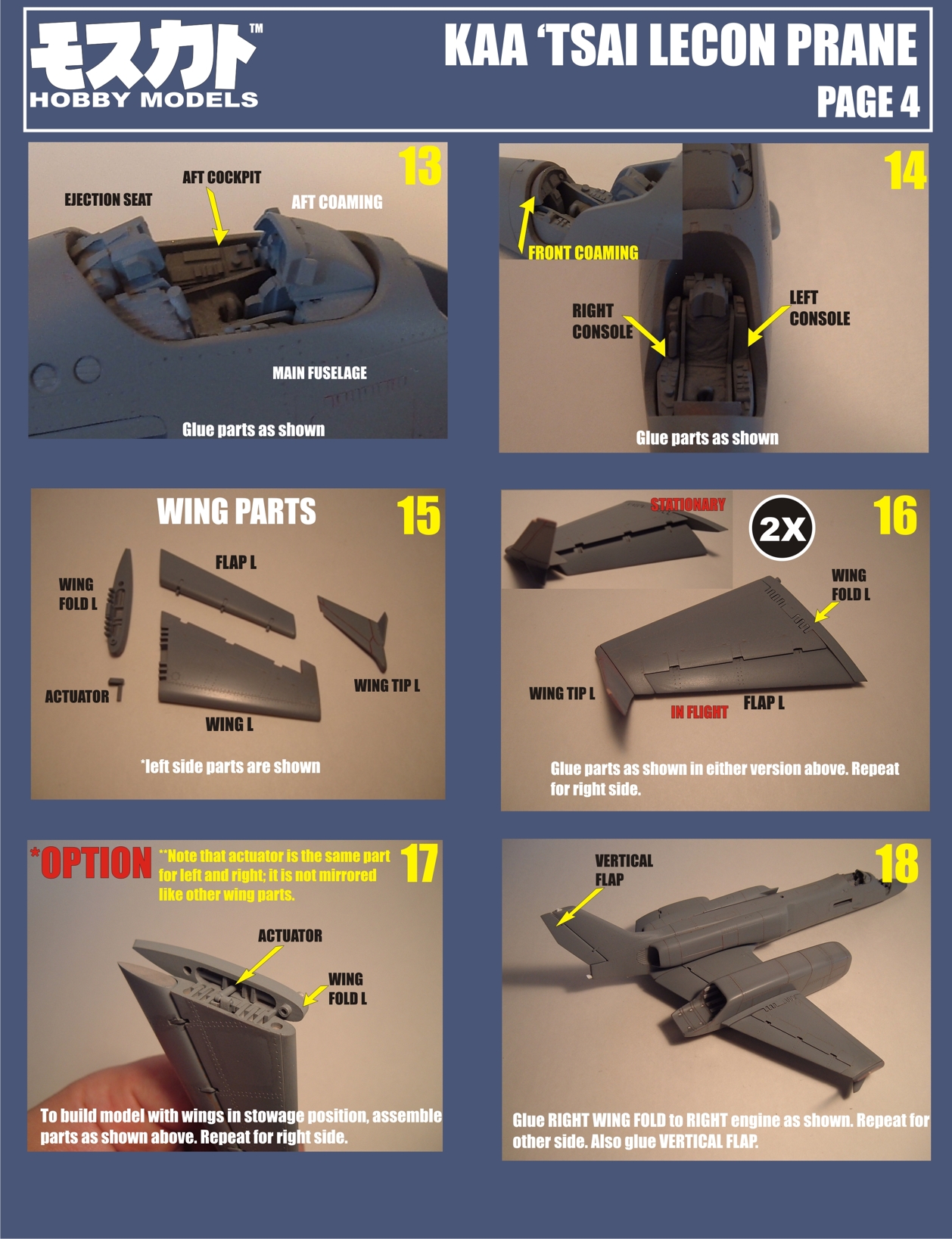
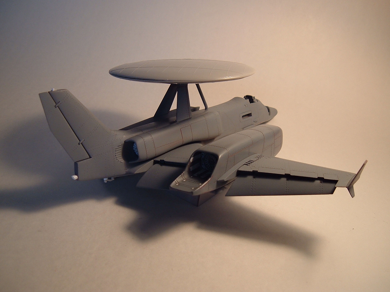
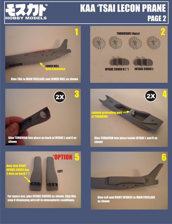
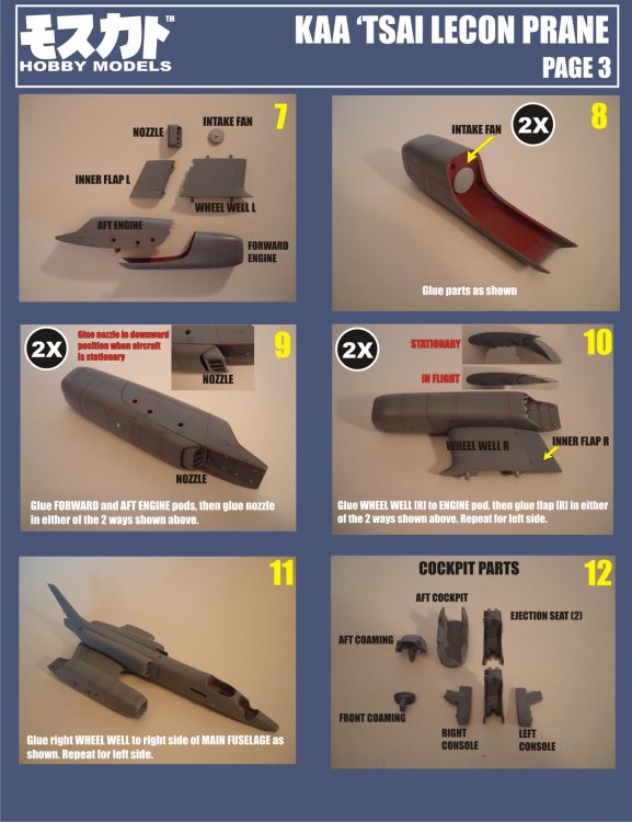
Undercarriage, flaps and engines.