captain america
-
Posts
3563 -
Joined
-
Last visited
Content Type
Profiles
Forums
Events
Gallery
Everything posted by captain america
-

Medicom/Hot Toys and all 1/6 scale figures
captain america replied to EXO's topic in Anime or Science Fiction
Does anyone know if the DX-12 Batman figure from Hot Toys is still available or being issued in small batches? I've had two on pre-order (paid) since Sept and the vendor keeps telling me that "it'll ship soon." I really think he's coitusing with me and I don't want to miss out on these. -
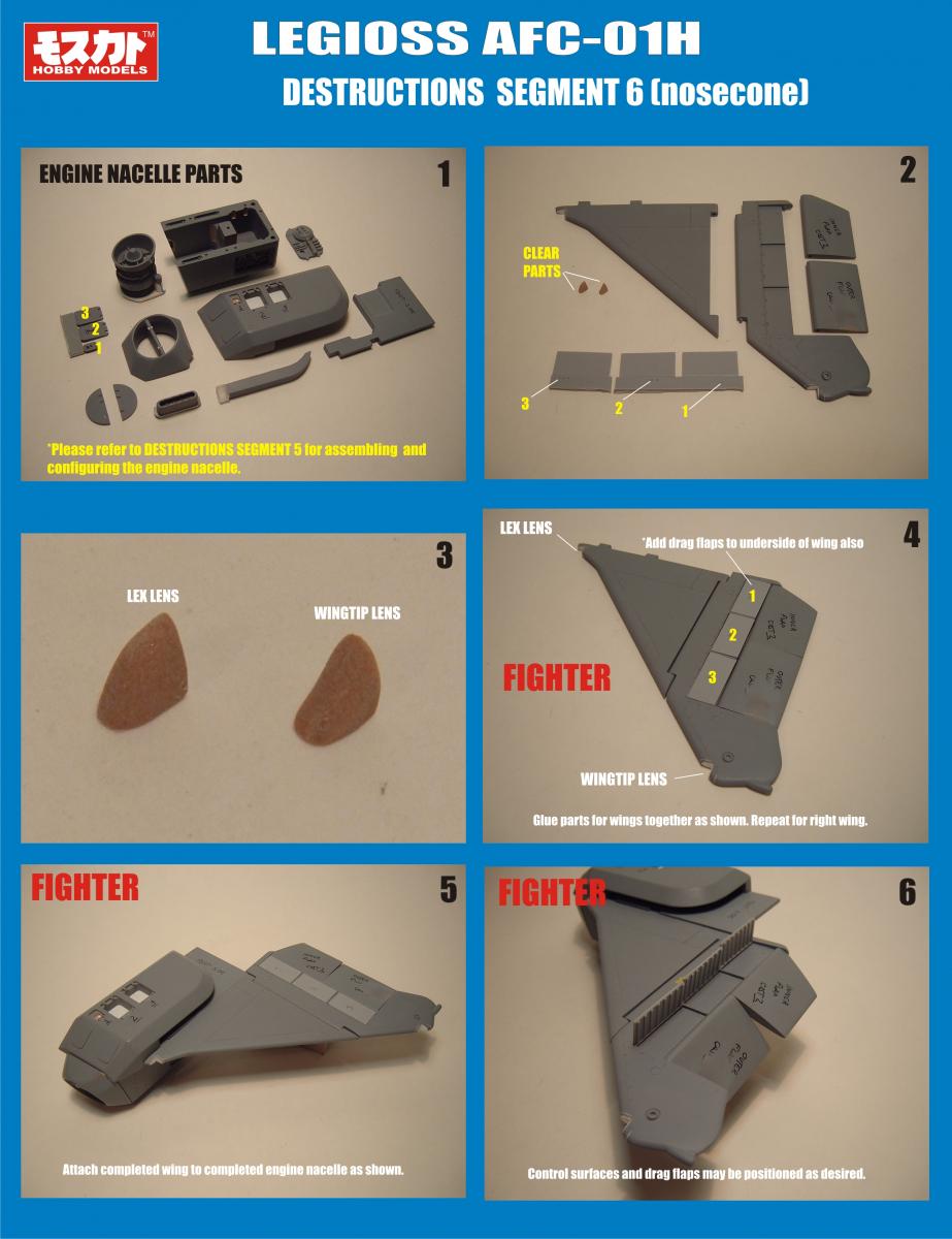
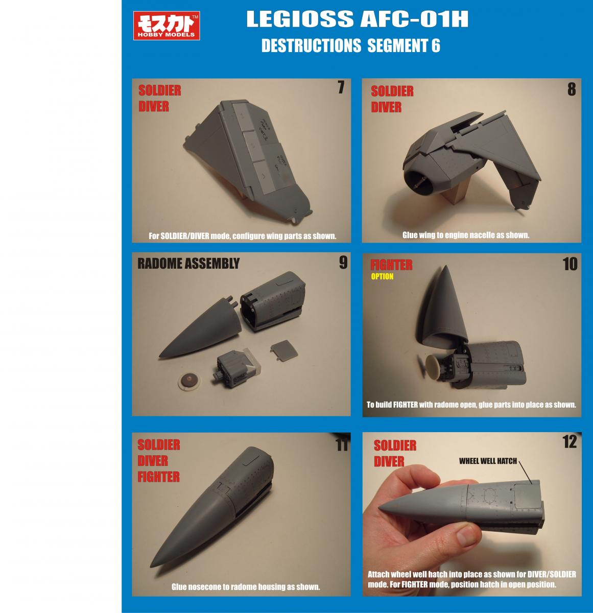
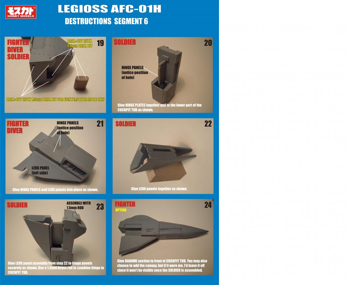
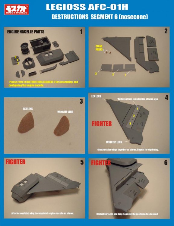
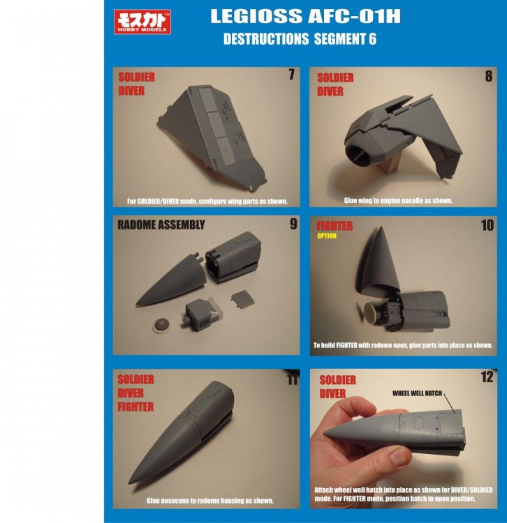
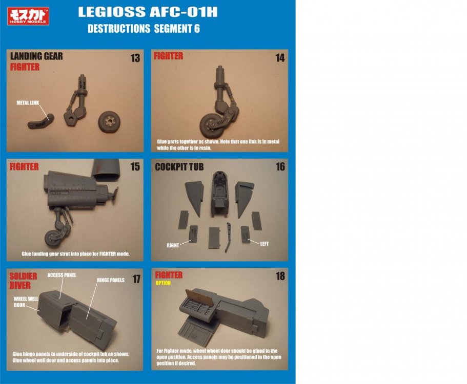
Fewer steps because some assembly sequences were covered in previous installments, plus the nose cone/cockpit isn't quite as complex as other sequences. I did mention previously that I have masters for sale. A Legioss re-issue with modified markings/heads would be a great project for someone willing to tackle it. Ignacio: LoL
-
You missed it, I posted the destructions for the nose cone back in summer, I think. Negative. My kits are packed away in my closet.
-
Hi everyone! I was wondering if there's anyone out there on MW that would be willing/able to do some 3D modeling for a little project of mine? I'd essentially need an object created that could then be output to a 3D printer, stereolithography, etc. I've created cross-sections using a vector design program but I know bupkus about working with more sophisticated programs. Please PM me if this is up your alley, will provide more details as needed
-
*Faints* *Regains consciousness* Holy crap that's amazing! The sheer size and the finishing are just... Wow!
-
Medicom/Hot Toys and all 1/6 scale figures
captain america replied to EXO's topic in Anime or Science Fiction
http://www.thehdroom.com/images/news/10976d.jpg More images here: http://www.thehdroom.com/news/Hot-Toys-The-Bat-Hulk-and-Catwoman-Make-Their-Debut/10976 Looks absolutely massive compared to a puny human -
Hi Guys. I'm not leaving, I'm still planning to hang around. I still love Macross, Mospeada and I think of this forum as a kind of second home. Just think of me as being "on vacation" as I devote my time to different projects. Sometimes the speed of the postal service is utterly shocking! I shipped Neptunesurvey's kits on Tuesday
-
I'm taking an indefinite leave from model-building in other to concentrate on other projects for the forseeable future. Will probably be unloading most of my master-patterns as well.
-
Looking good, Mike! Hopefully people will take an interest in what I think is an awesome project! On a somewhat related note, I've started packing boxes and will be shipping this week starting tomorrow. Any changes of address should notify me ASAP if you haven't already. Finally, my hallway will be box-free!!
-
Hi everyone! Just wanted to let you know that the canopies and composite joints have finally arrived safe and sound! You heard me right, this is not a joke! I'll begin packing all the parts during the upcoming week and begin shipping in due course. Before I do though, I would ask that those of you who have moved in the last year please PM me with your new info so that I don't end up sending the parts to an outdated address. It seems that fate could not stop me from completing the Beast after all...
-
I see I wasn't the only one praying! LoL Whenever I hear stories about parcels lost in transit 98% of the time it's never good. Guess we all dodged a bullet on that one.
-
Hi everyone. My sincerest apologies for the long silence. I just got off the phone with Chris earlier, and the post office found the lost parts and they've been returned to him. I should be receiving them by the end of next week. A light at the end of the tunnel, finally!!! Also, Silverdragon will be embarking on a project to make alternate heads for The Beast, as shown by his diagrams above.
-
Spoke to Chris earlier this week. Seems that the parts have been shipped but somehow got lost in transit. There's a postal investigation goin on on his end and now we're waiting to see if the parcel can be found or if he'll need to make a new batch.
-
Hey everyone, I have some great news! I finally managed to contact Chris earlier tonight and touch base with him. As per what he told me, he's been having some personal issues to deal with, which is why he hasn't been on the forums. It seems that all the parts are done and about to be shipped, so with any luck I'll have the final parts in the next 2 weeks.
-
Still having trouble contacting Chris. I really don't know what to do from here: it already cost me a substantial bit up front to get him to work on the parts and now he's leaving me hanging...
-
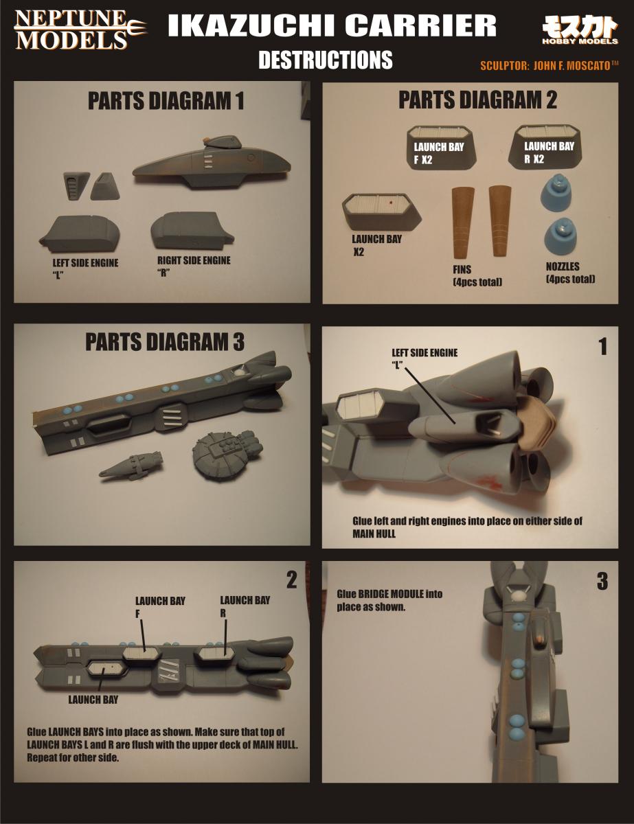
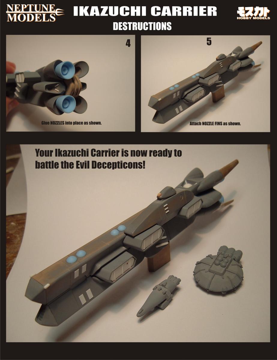
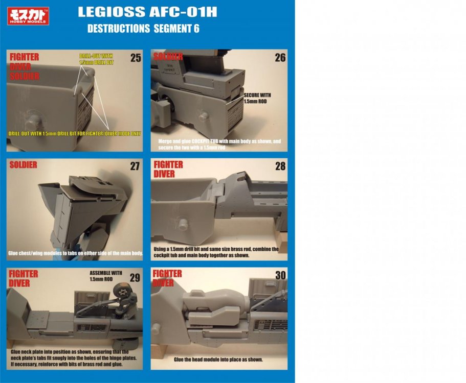
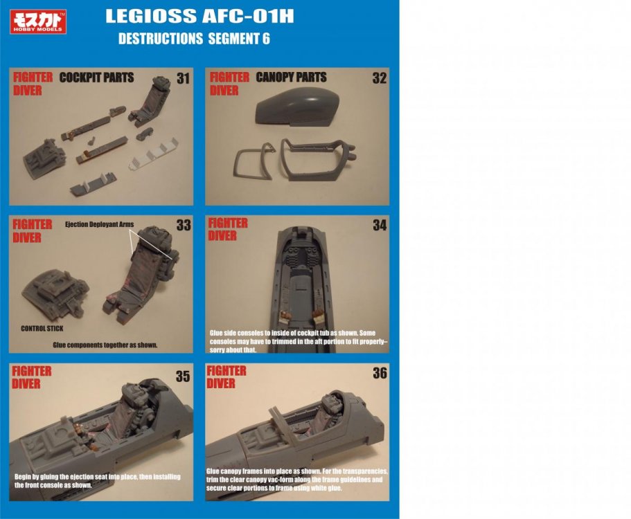
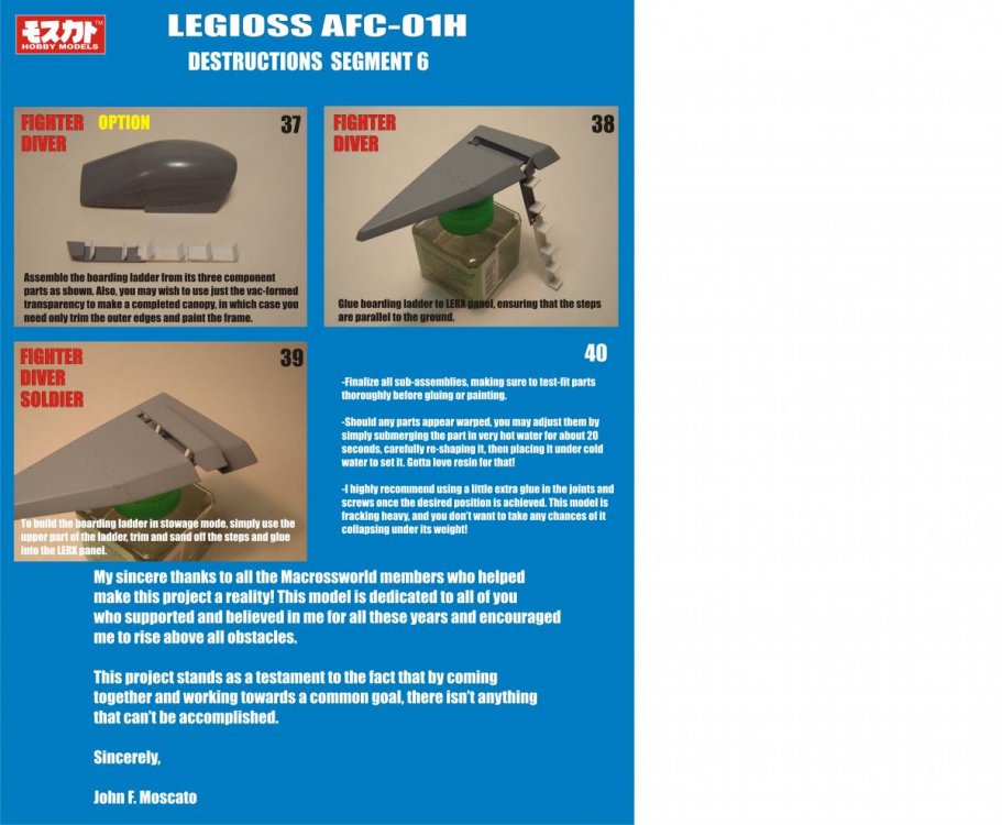
Beast Destructions: The Final Curtain!
captain america replied to captain america's topic in Model kits
The joints, their assembly and positioning for various modes are shown in the segments for the legs and the main body... I just haven't received the final production parts yet. -
Hi guys! While I'm still obviously waiting on the last few subcontracted parts for the kit, I thought I'd at least post the instrutions for the final segment to wet your appetites. To be downloaded as per usual And the last 3 pages.

-
All the composite joints and the canopies.
-
A Little Mospeada Love!
captain america replied to captain america's topic in Anime or Science Fiction
Just wanted to let everybody know that I've been without internet or phone service for nearly 2 weeks and it will probably continue for another week still. I have shipped all orders placed until now but due to circumstances beyond my control, I won't be taking any more orders for these kits. -
I've been trying to reach Chris Barretta about the parts he's supposed to be making for the kit but so far I've just been met with silence. If anybody knows of his whereabouts, please let him know that I'm still waiting.
-
A Little Mospeada Love!
captain america replied to captain america's topic in Anime or Science Fiction
I don't do commission builds but I'm sure that if you ask around the modeling or customs forums you'll be able to find people that will be more than happy to offer you their building services. -
A Little Mospeada Love!
captain america replied to captain america's topic in Anime or Science Fiction
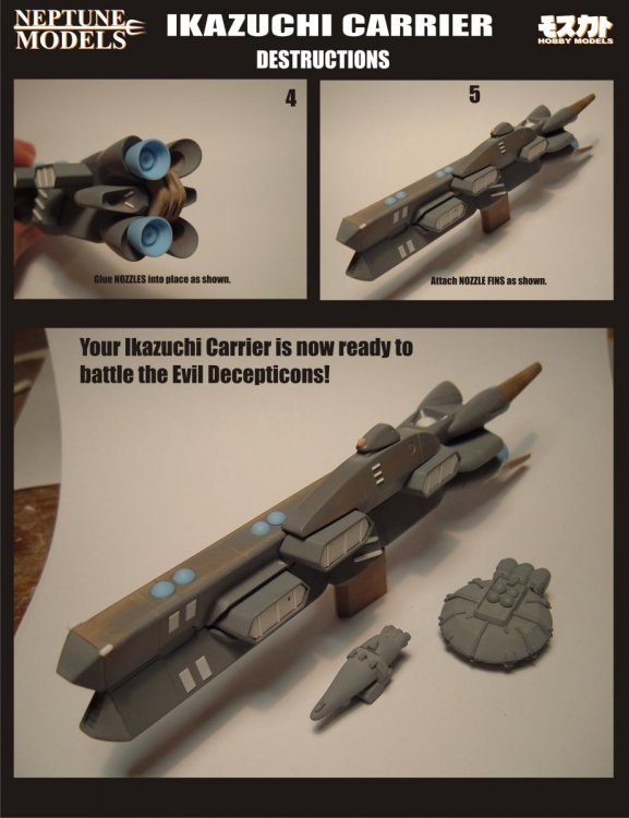
Oh, and here are the kit destructions ready to download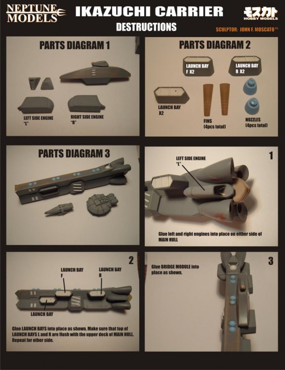
-
A Little Mospeada Love!
captain america replied to captain america's topic in Anime or Science Fiction
I can't honestly recommend a garage kit if you're not at least somewhat proficient with regular plastic models. -
A Little Mospeada Love!
captain america replied to captain america's topic in Anime or Science Fiction
Hi everyone! Well if you're looking to procure an Ikazuchi kit or two, then this post is for you! I have roughly 12-15 kits available at $50 CAD a pop. (yes, Canadian dollars) Shipping: $13 CAD for up to 2 kits shipped within Canada/USA. Overseas: $25 CAD for up to 2 kits. Payments can be made via paypal by following the instructions below. Please read carefully. Payments must be in CAD funds ONLY, no exceptions. Payments not in Canadian funds will be returned. Paypal doesn't charge fees when you send a payment as a "Personal Transfer", so please use this instead of purchase payment/consumer purchase. The only caveat is that the funds must be drawn on your bank account or from your paypal balance. If for whatever reason you can't use this feature, please add 4% to the total to cover the paypal fees. If you don't have my paypal info or have any questions, please feel free to PM me as always -
A Little Mospeada Love!
captain america replied to captain america's topic in Anime or Science Fiction
The MWer who commissioned this project from me should be weighing-in shortly, as they'll be the one to discuss price with. I'm just a subcontractor on this one Wagon wheel: yeah, my folks were redecorating and had these old western-style light fixtures that they were just going to throw-out. I just loved the look of them and couldn't bear to see them discarded so I adopted them.