

captain america
-
Posts
3550 -
Joined
-
Last visited
Content Type
Profiles
Forums
Events
Gallery
Everything posted by captain america
-
I'm happy to see new plastic kits being made of these classic designs like the Q-Rau, though one aspect I think Hasegawa really fumbles the ball in is surface detailing. Zentraedi weapons are (based on the information gleaned from watching the series) very old and seemingly crude but very reliable. The new movie Q-Rau plamo utterly fails to depict that. The missile hatches, sensor blobs and "greebly" bits all look like modern manufacturing: neat and clean. I believe something more akin to Soviet-era aircraft would be more fitting (buckled and ill-fitting panels, crude rivets, etc.) But I guess for the price, they have to cut corners somewhere.
-
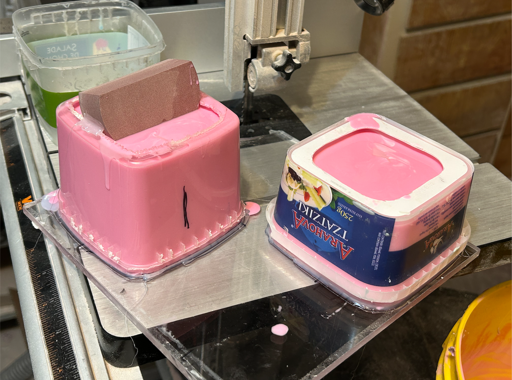
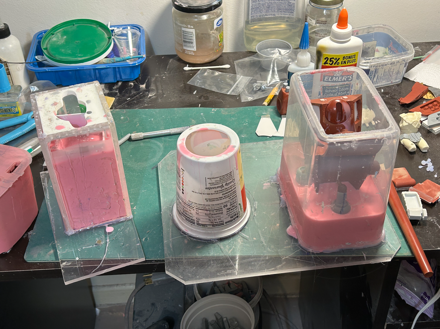
Speaking of pink goo, I haven't drowned in it yet!! The long silence is merely due to the utter volume of mold material I've had to pour over the last week. 16 molds and > 20 lbs of pink goo. Test-shots have come out great, but pics will only come early next week.
-
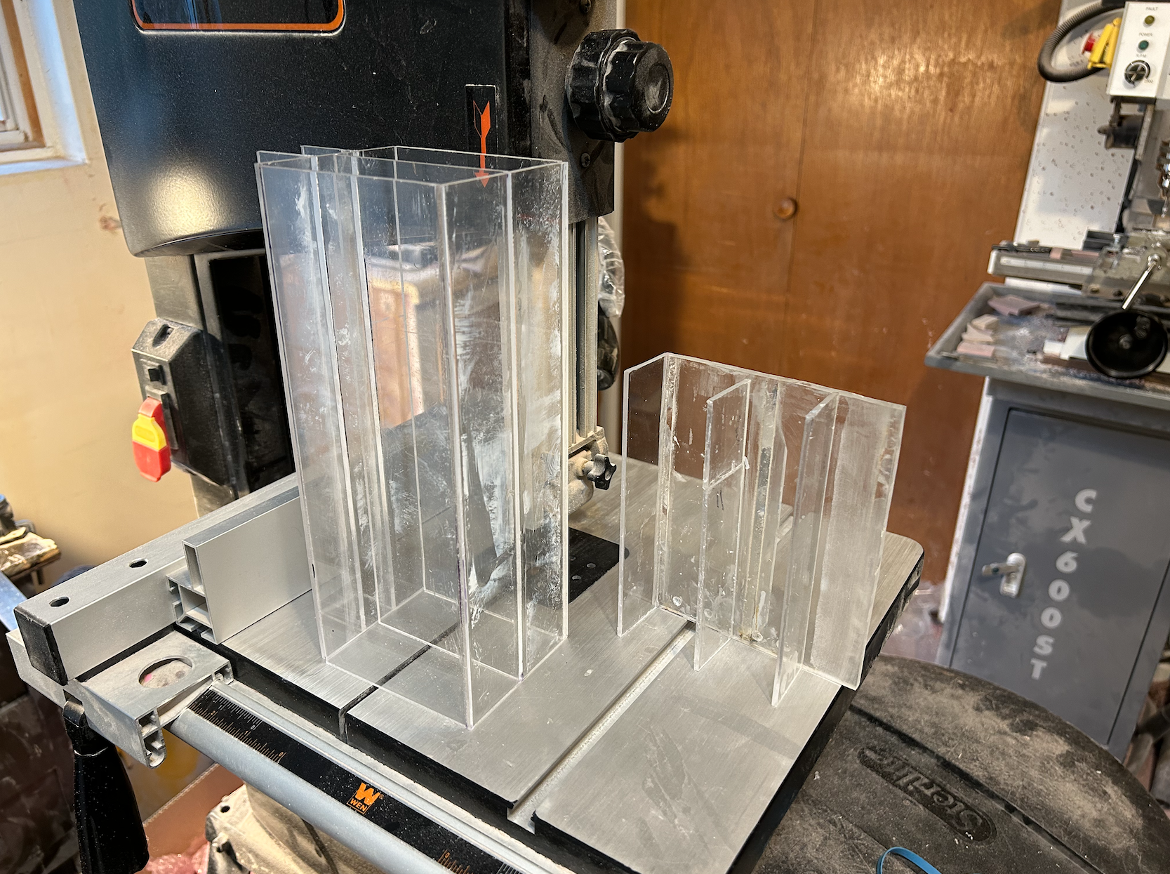
Captain's log: Wednesday, September 27, 2023 Apologies for the long silence, I've had some logistical challenges to overcome, but I've been diligently working on the molds, which are in full-swing. Because some parts are not only large but oddly-shaped, I've had to construct custom mold boxes to hold those parts. A task hindered by the fact that the intermediate owner of the masters failed to give Brett the master-castings I made for all the duplicate parts—requiring more time and effort for preparation. Alas, things are moving along well. Proofs the decals look fantastic, so a massive thank you to Devin for being able to print these on such short notice. Assuming all goes to plan, I should have the molds done by the end of next week. Stay tuned!

-
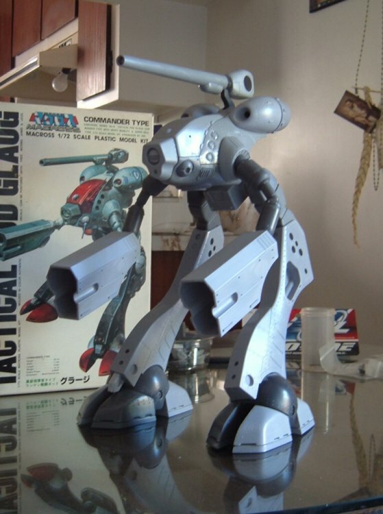
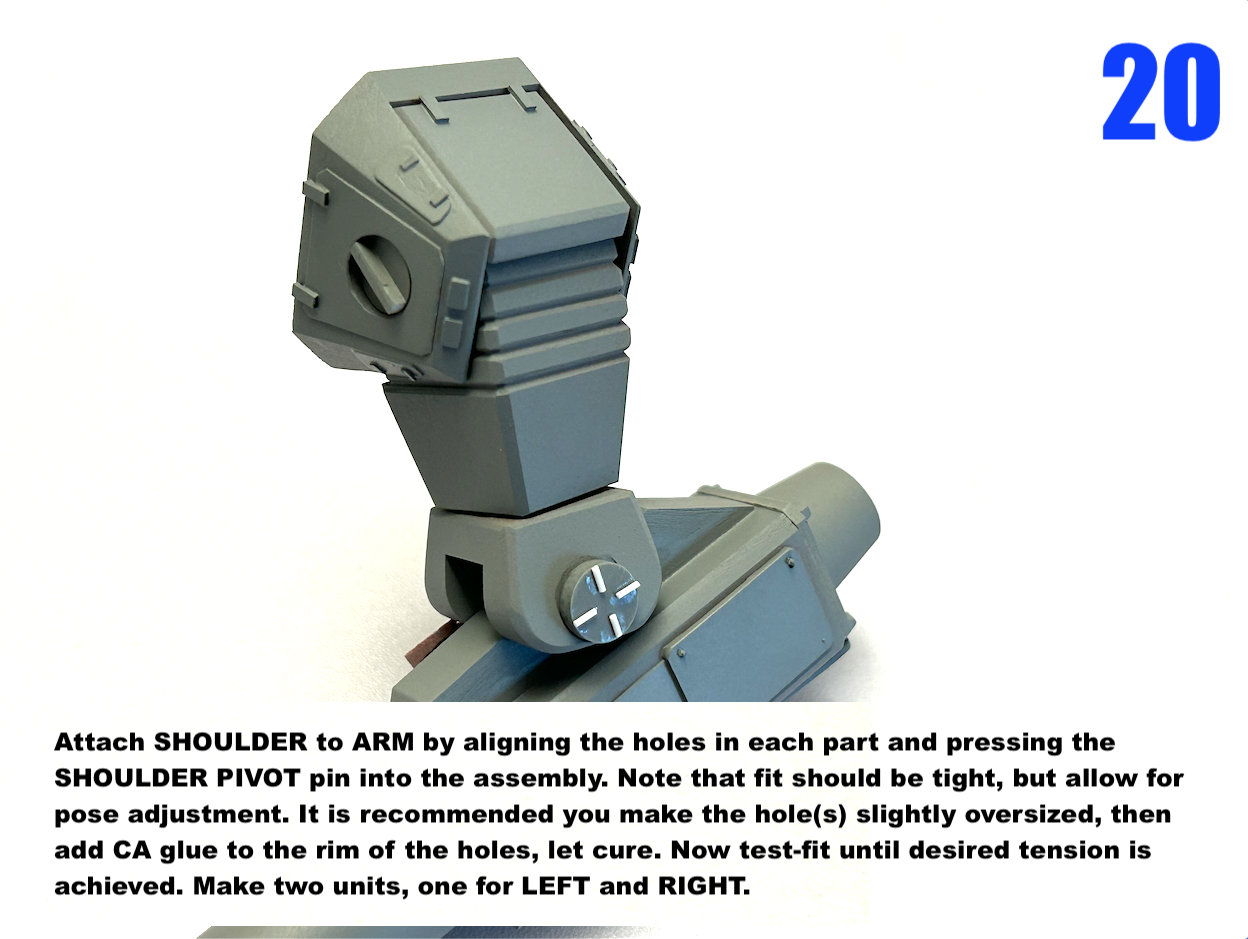
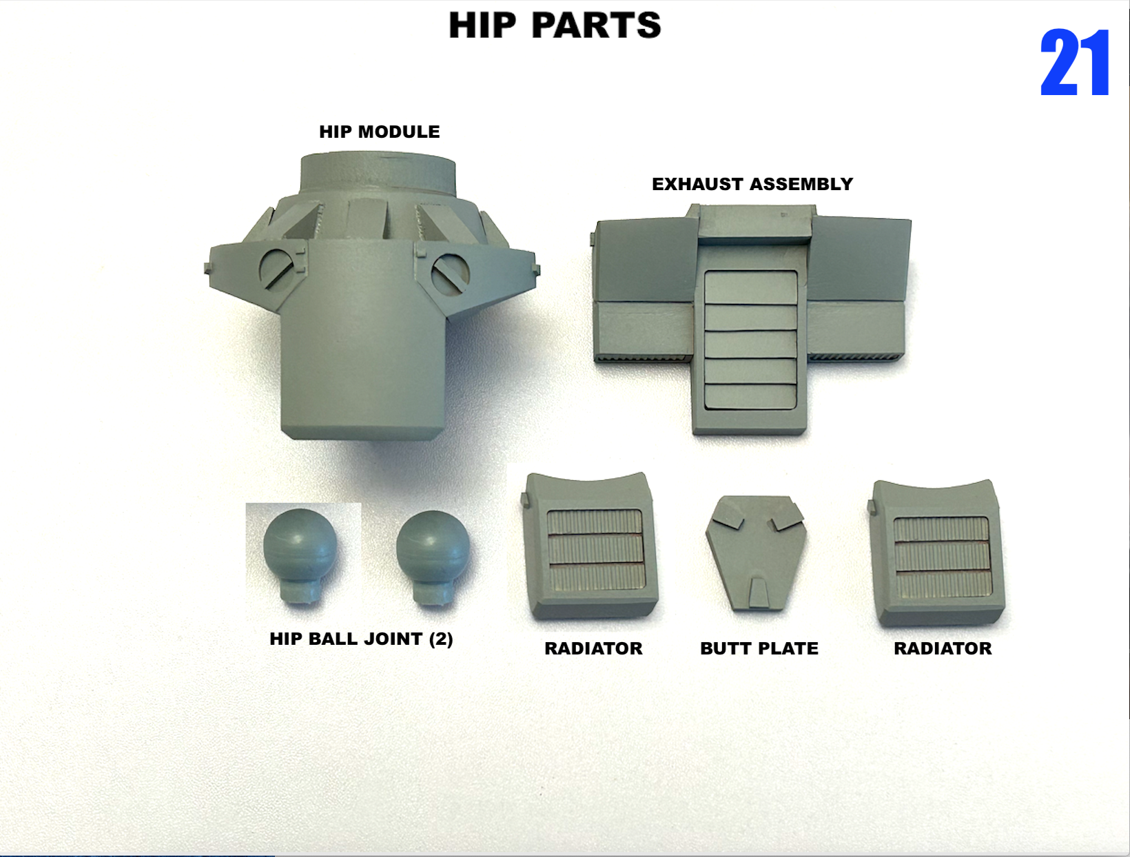
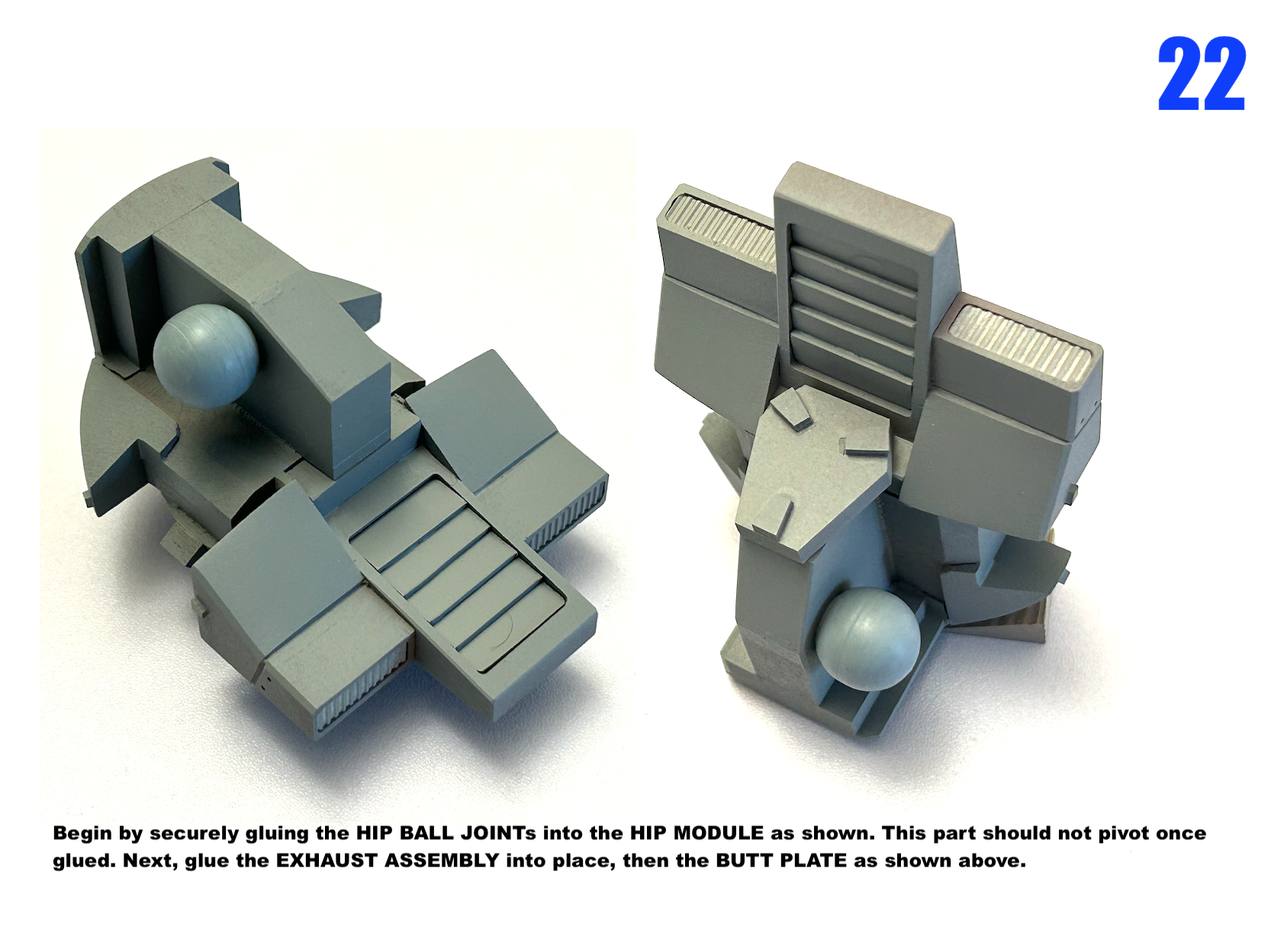
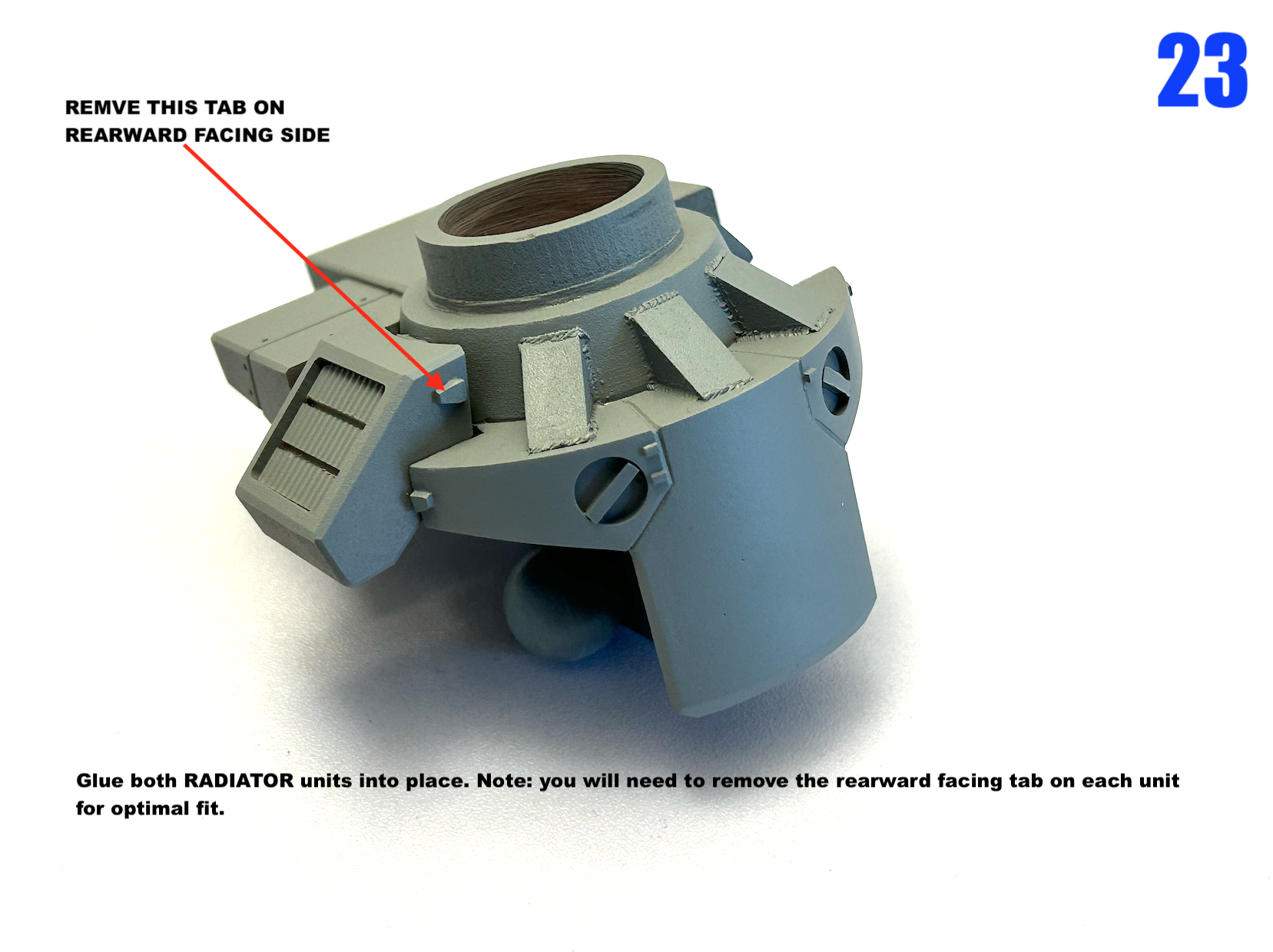
Roughly 35cm tall. I think the (over)engineering holds-up fairly well. The struggle is in that middle ground where you want to make things as easy to cast as possible, but still have enough of a parts breakdown to facilitate painting.
-
Final call for this baby! The deadline to get in is noon September 18th Eastern time and I'm closed Sundays, so move it or lose it.
-
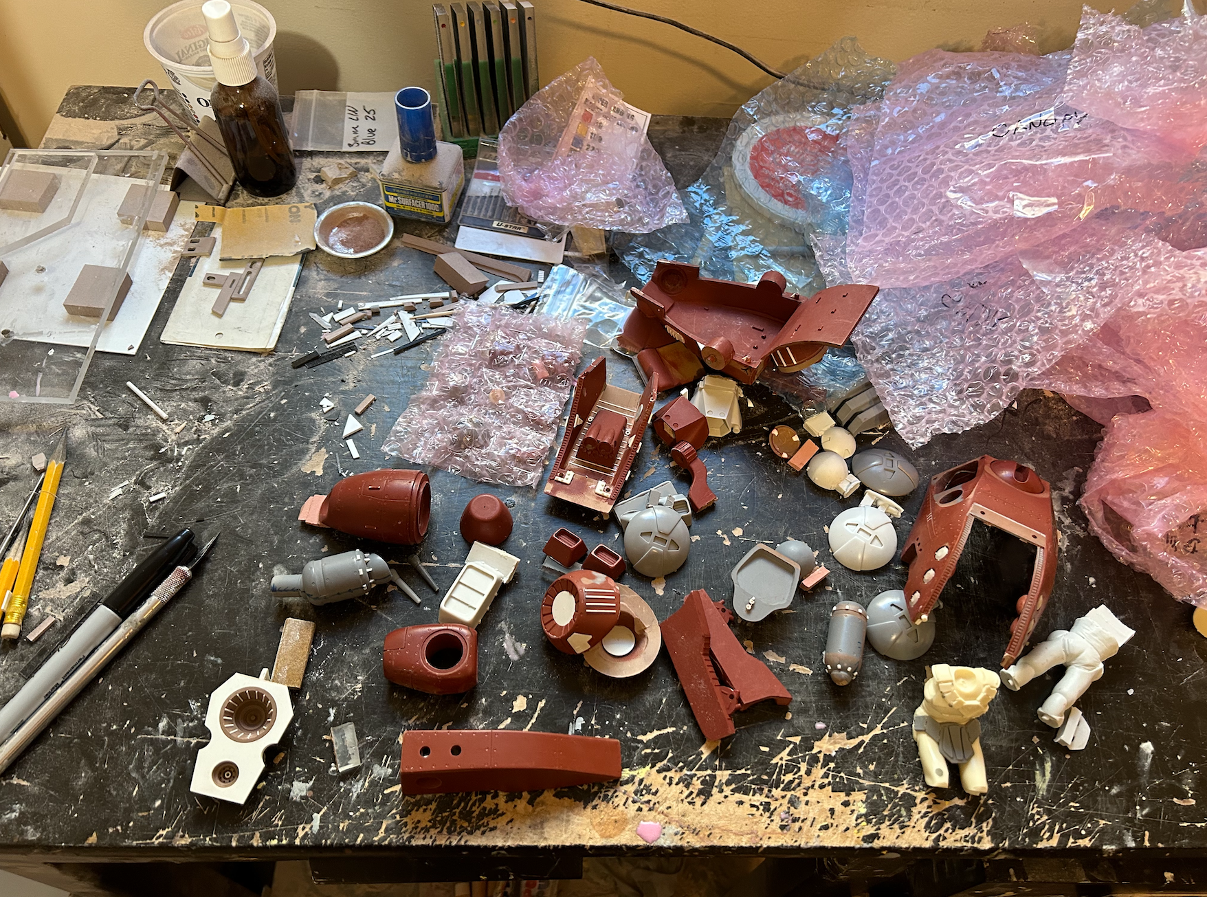
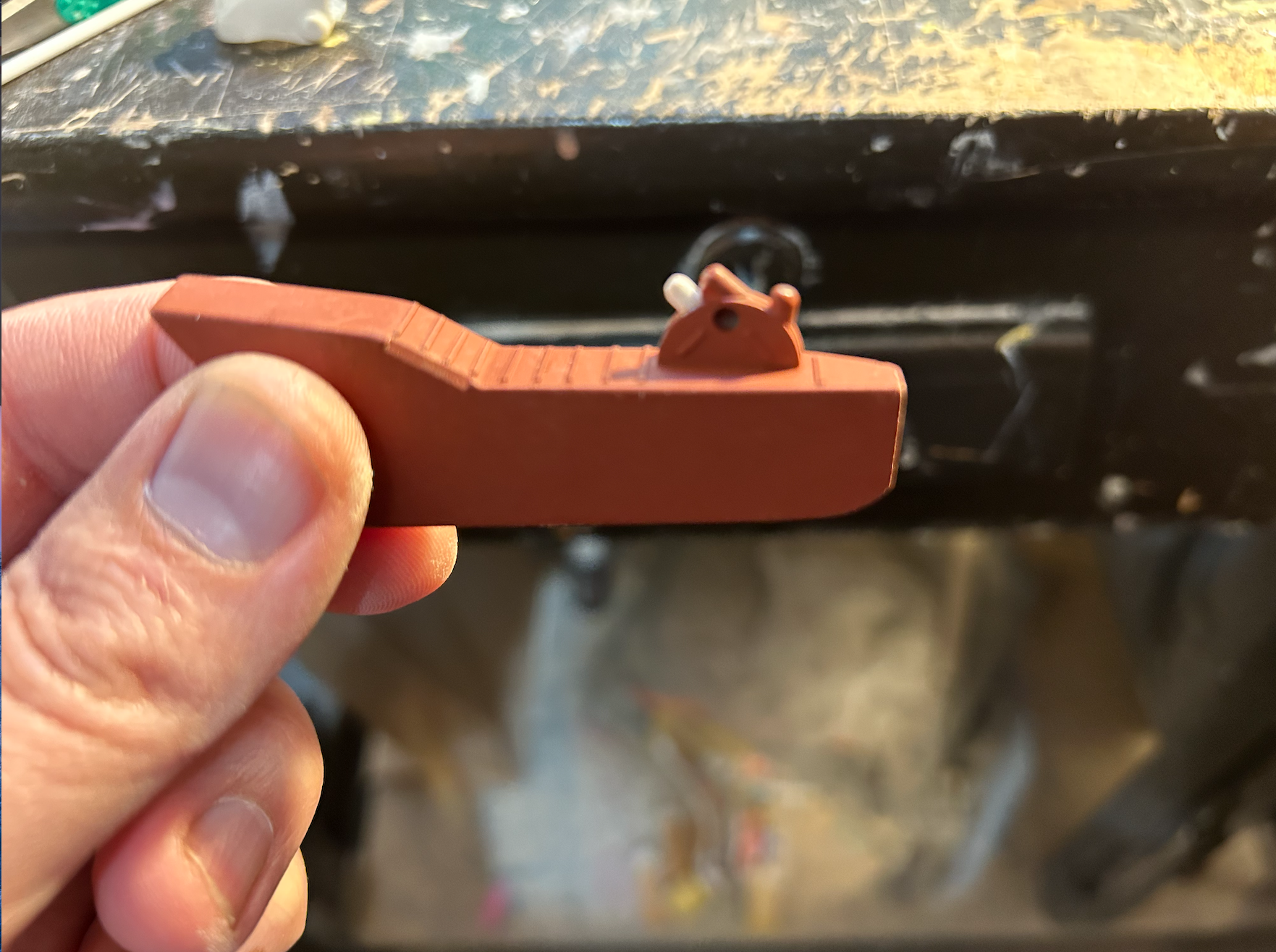
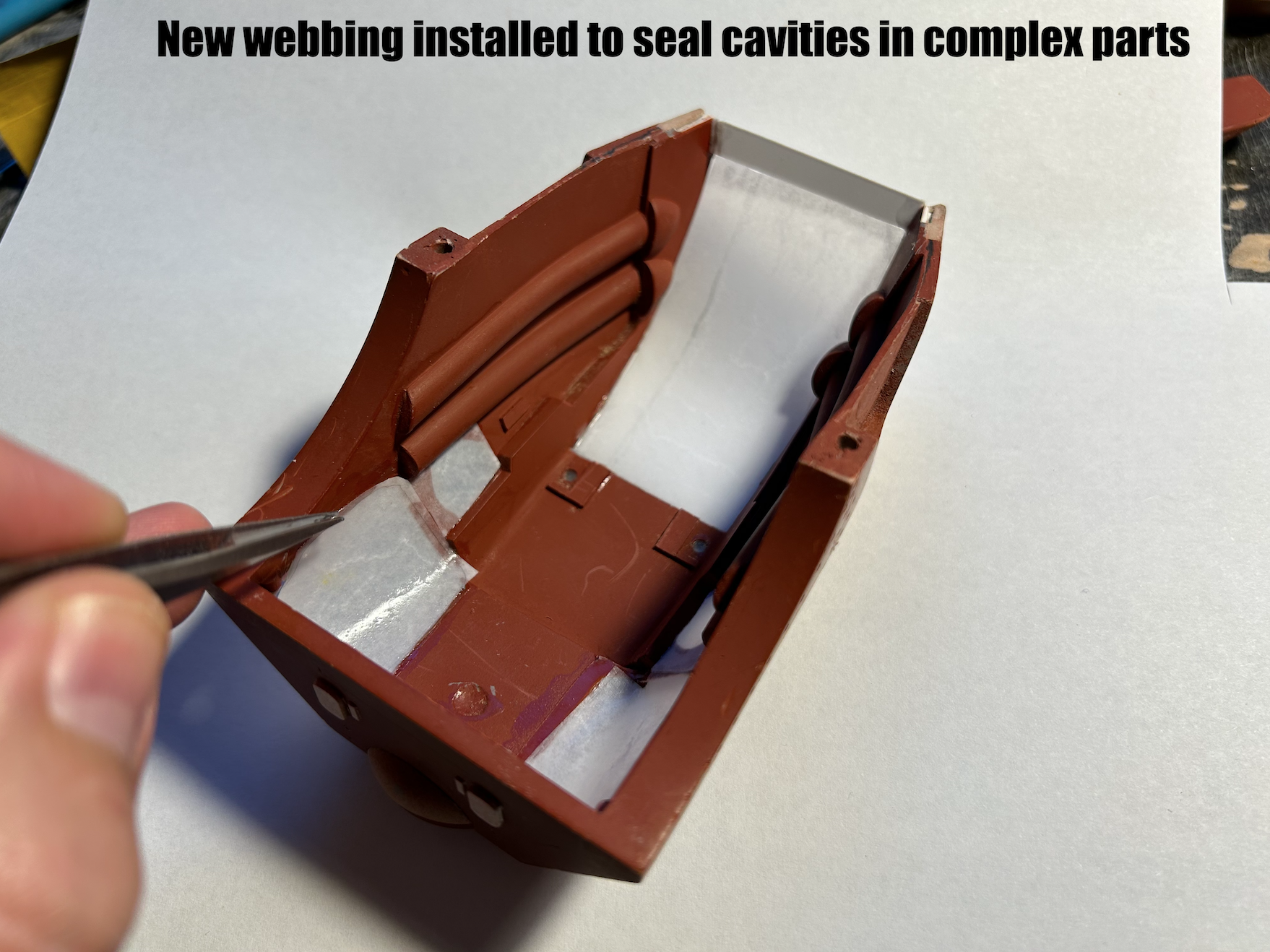
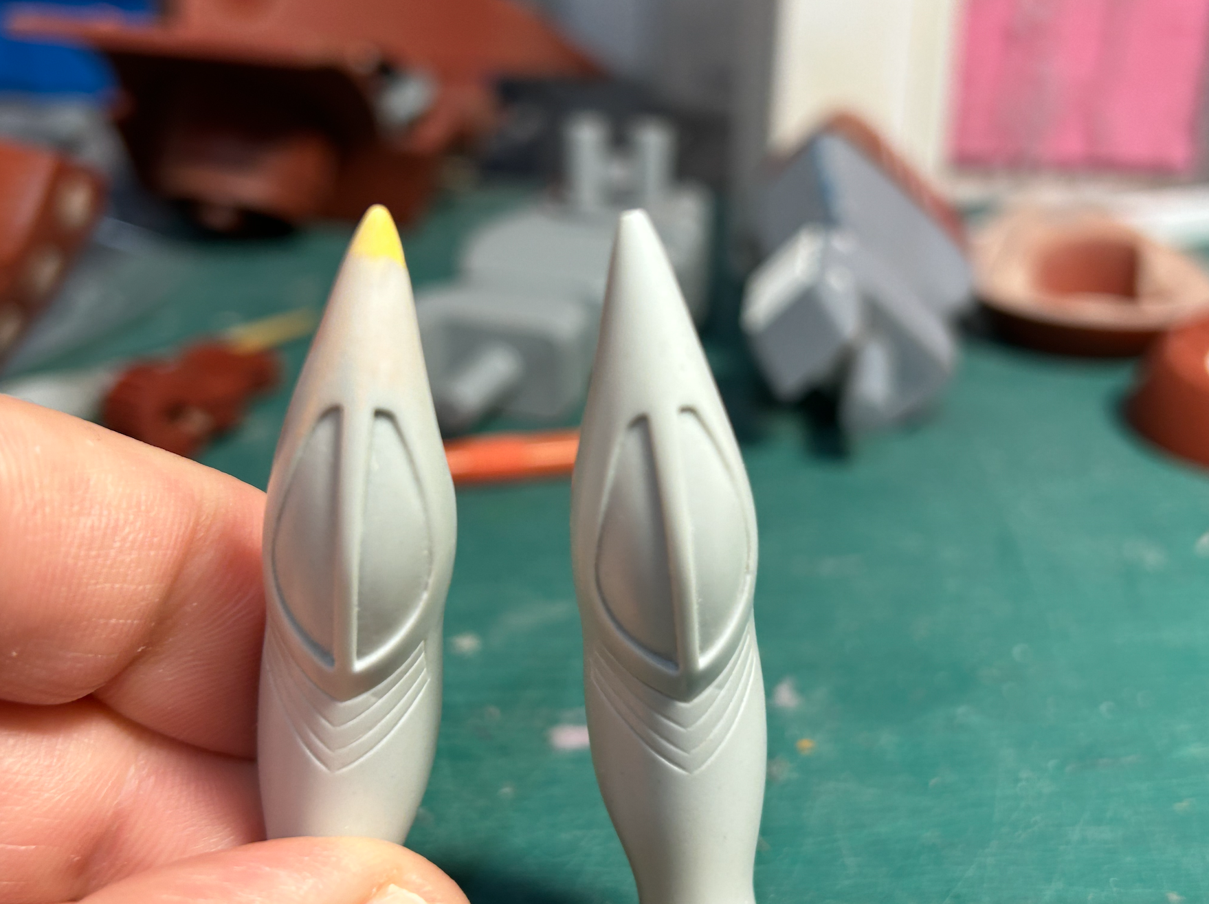
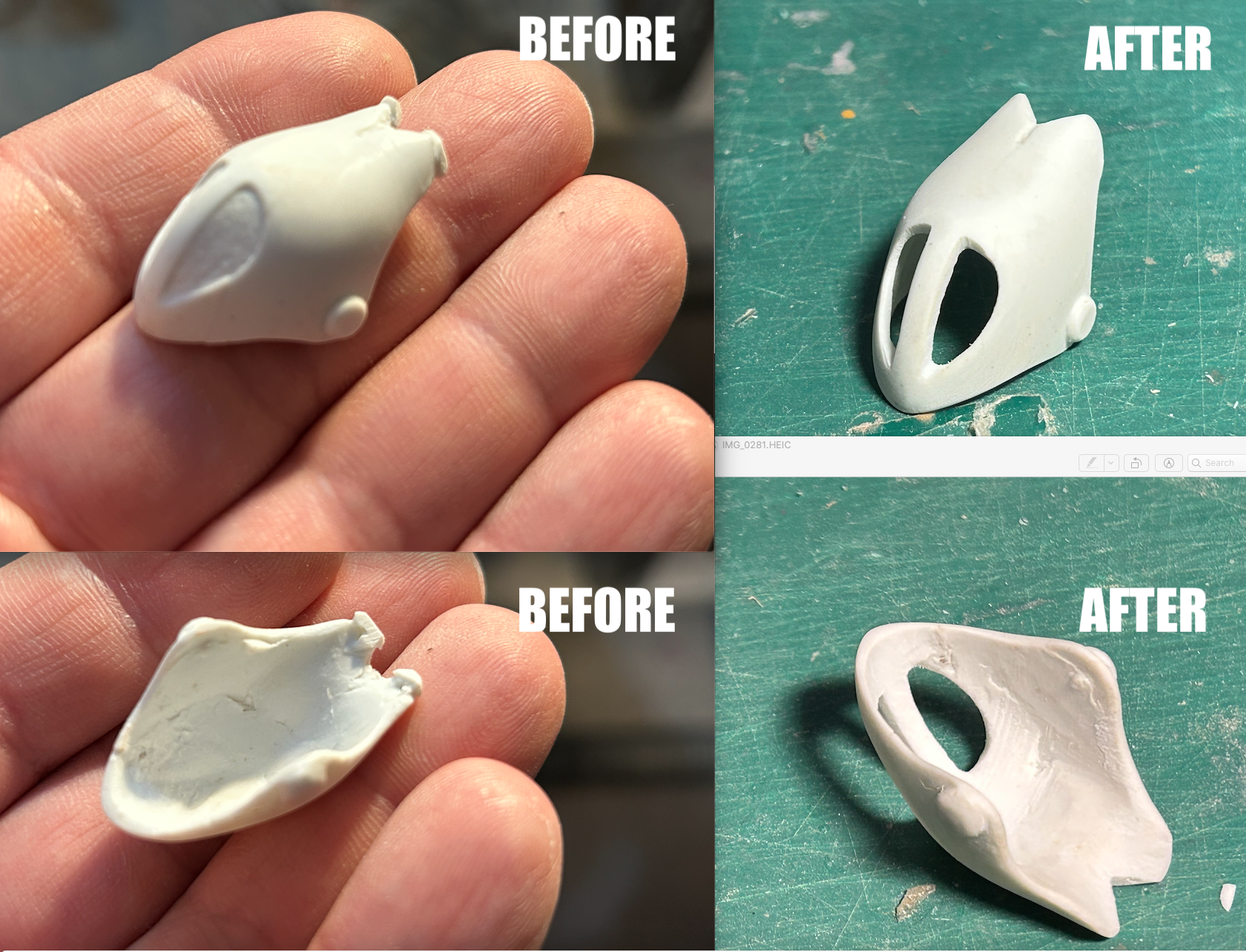
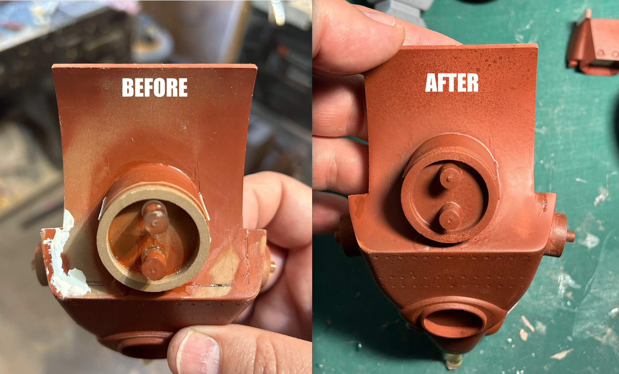
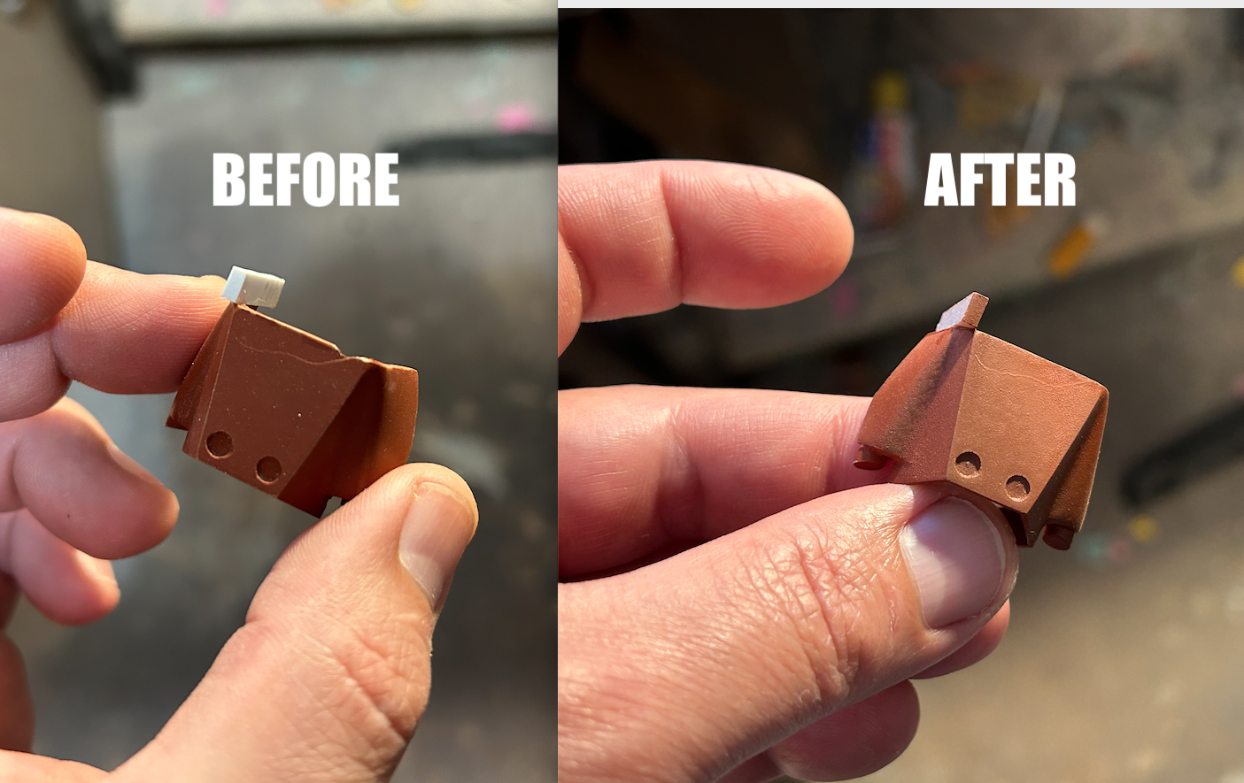
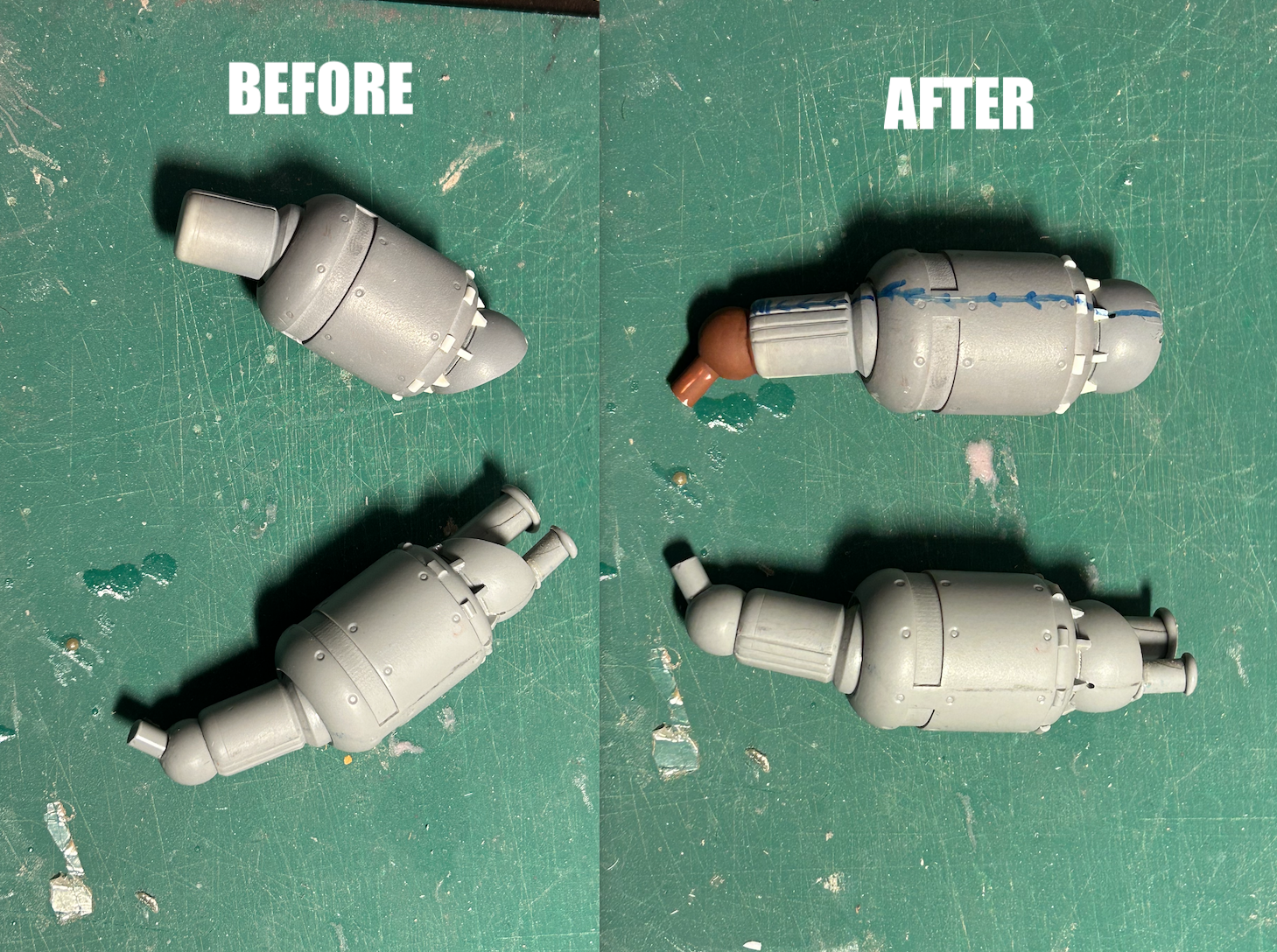
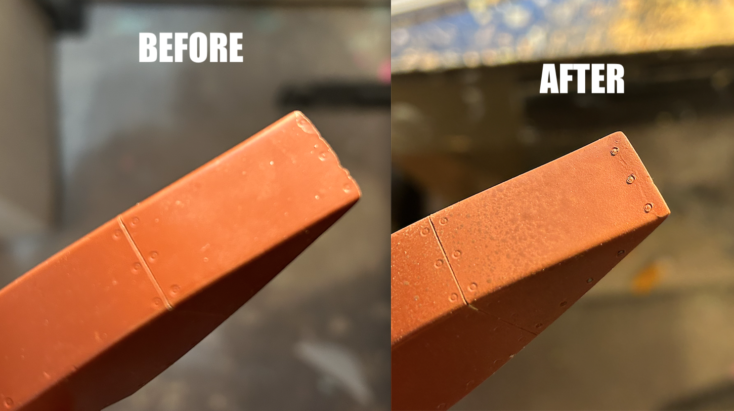
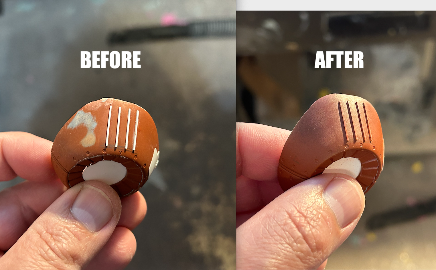
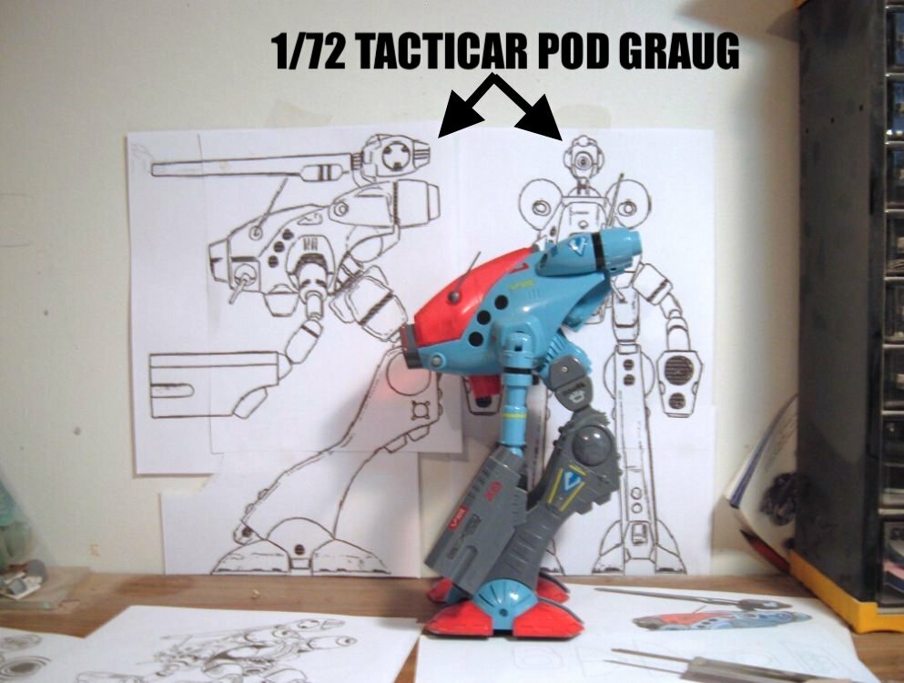
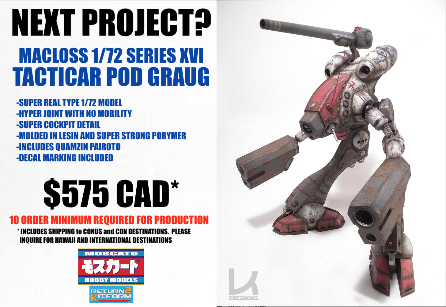
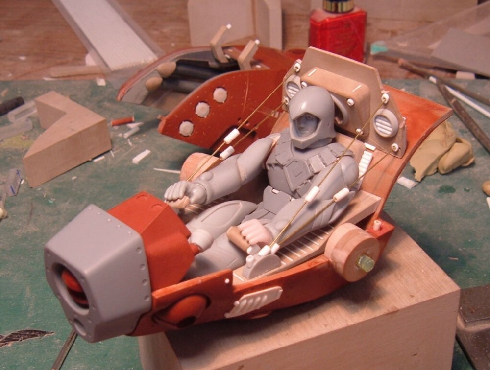
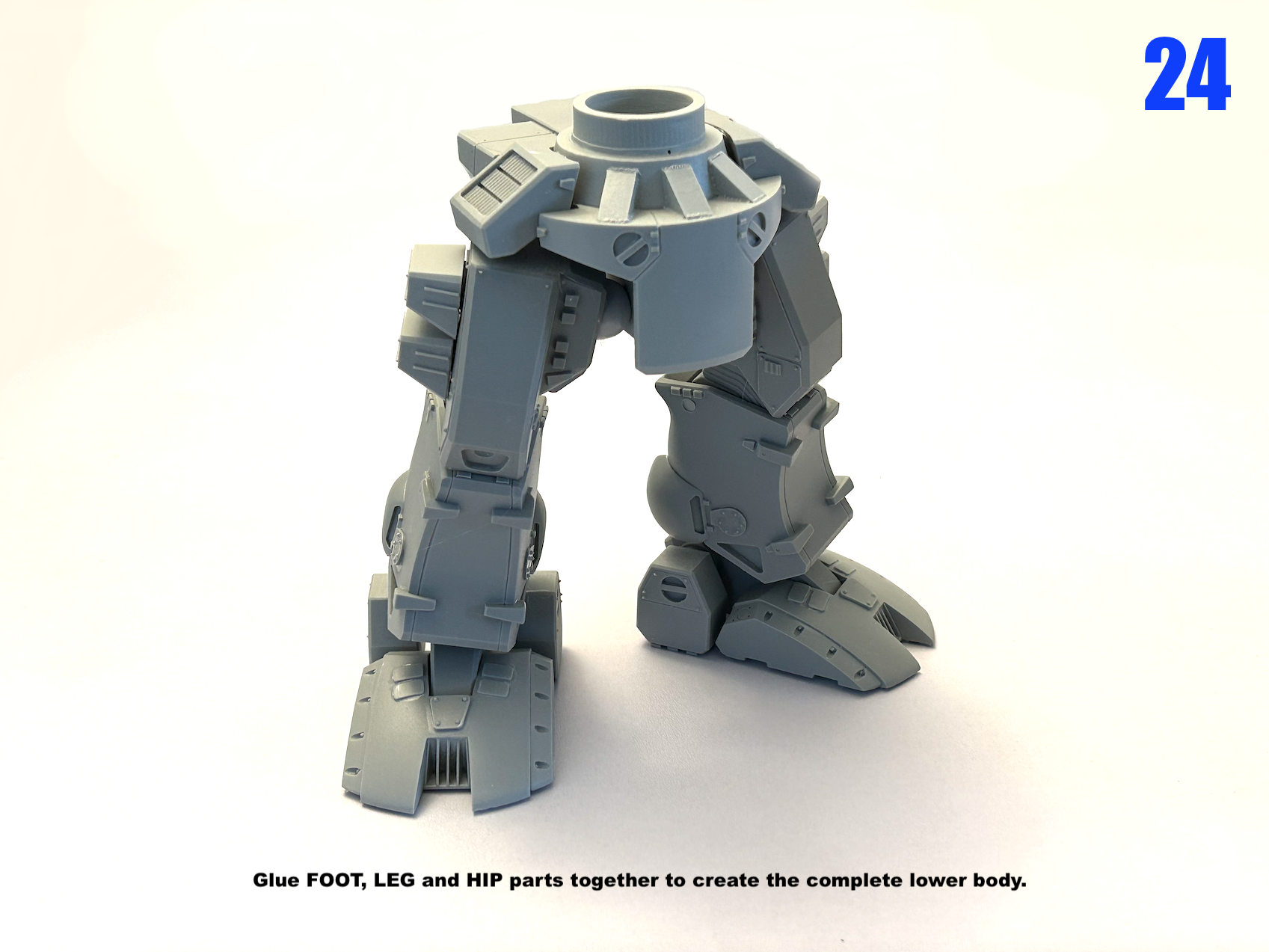
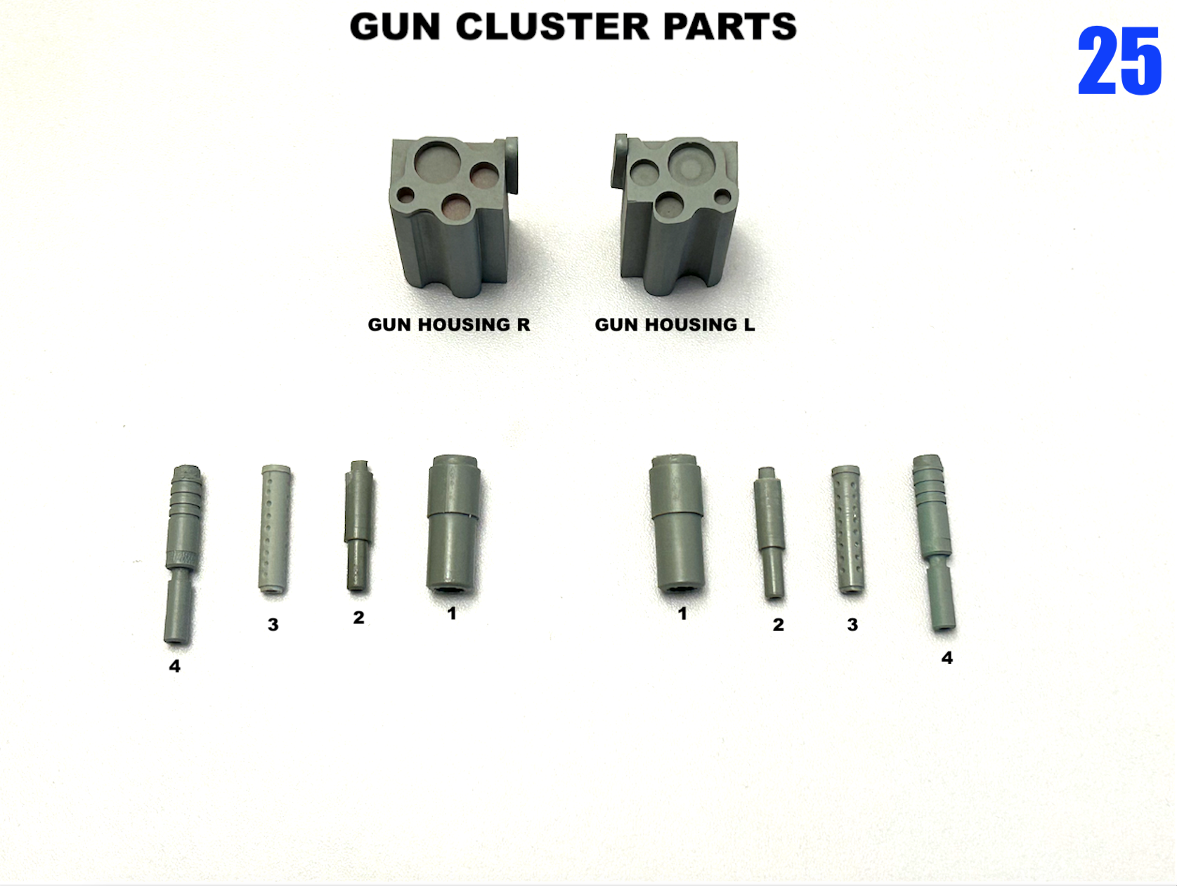
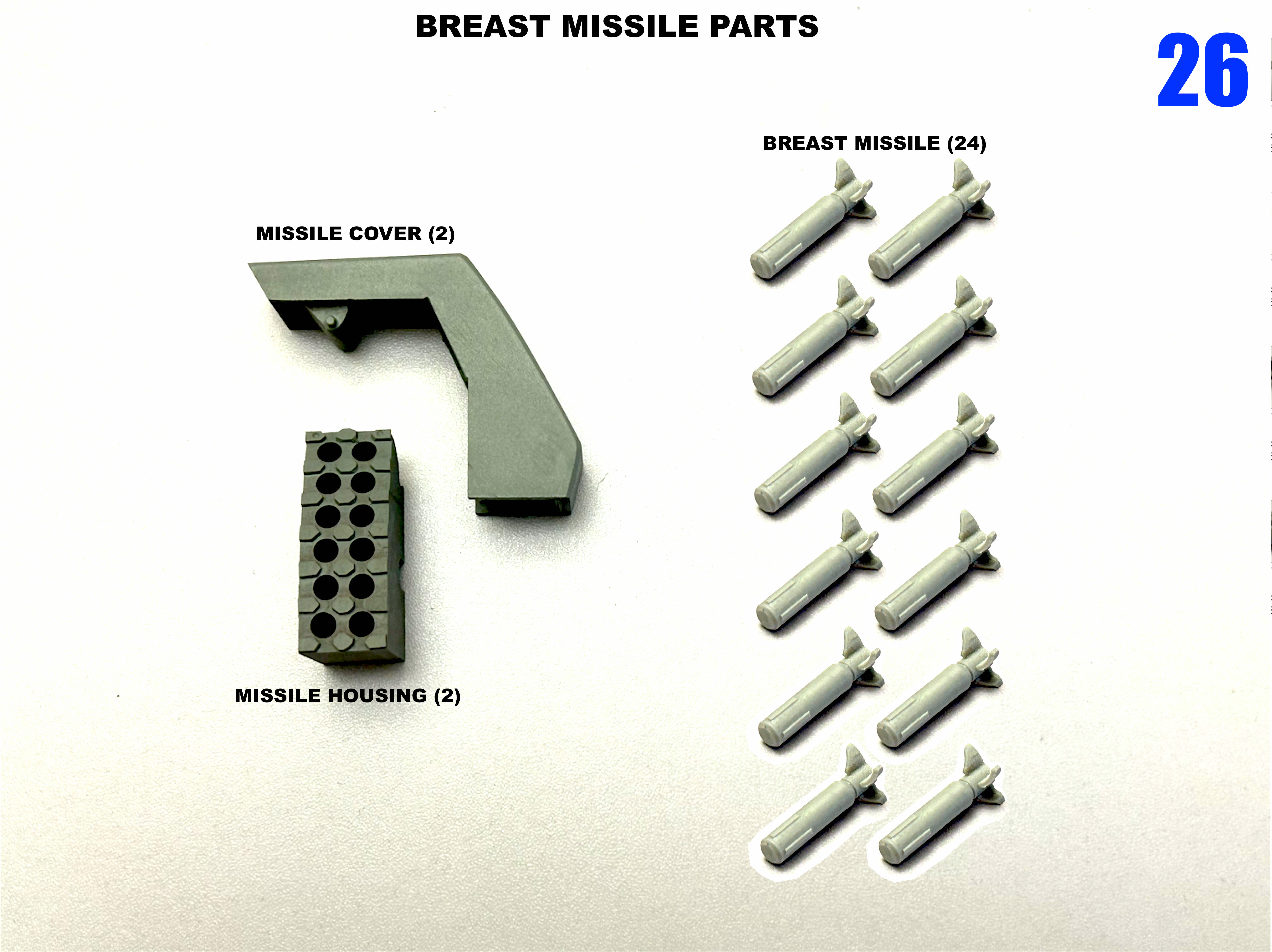
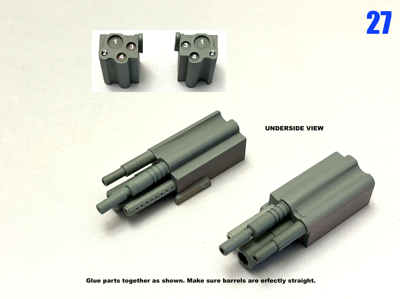
Captain's Log: September 7, 2023. Time flies! I find myself unpacking a box of master-patterns I haven't seen in 14 years—the Tacticar Pod Graug! Oh, the memories of things long past. To my knowledge, they'd been sold to someone who tried to get a run of kits going, but may not have been entirely successful, so Brett over at Return 2 Kit Form was able to acquire them for a reasonable price. Upon inspecting the parts, I can understand why. Some of the patterns had become damaged with use, and repairing them wouldn't be an obvious task, given that much of the detailing was done with my own custom-made tools. With Brett's approval, I had the masters sent to me for inspection and refurbishing. Aside from a few missing components and molding fractures on the hull, most of the damage was minor, but scattered across multiple parts. Not an easy task, but not impossible. I was able to restore the surface rivet detail using the same custom-made punch I used 14 years ago, and with a little elbow grease, all the little dings and cracks are repaired. One component which probably didn't survive the molding process was the pivoting armored face shield for the helmet. It was a rather thin part to begin with, and what came in the box was a very crude casting of the part which looks like it had been filled with a generous amount of putty to plug the eye holes and make the casting thicker and easier to manage. Thankfully, the resin is forgiving, so I was able to re-carve and shape the component to where it now fits on the helmet and looks the part. The next step will be to prep and seal all the parts for molding, and the construction of some custom mold boxes to handle these massive components. Stay tuned!

-
You'll have to remodel all the surface detailing on the shin armor, forearm armor, face, mono-eye, antenna and feet. They have a similar shape but the details are very different.
-
That's the Matchbox toy. I have pic to compare with the ARII 1/72 box.
-
For those who weren't around back in the day, know that this is a BIG model!!
-

No Love for Southern Cross?
captain america replied to blacklotus's topic in Anime or Science Fiction
It looks a bit floppy, but I chalk that up to a natural byproduct of hand-made variable models. I'll give him credit: it's the best rendition I've seen in 3D so far. -
Top Gun: Maverick (Top Gun 2 is comin)
captain america replied to Ladic's topic in Anime or Science Fiction
This is the way. -
Good grief!! I guess they threw human anatomy right out the window with this clown design. Had it been purely a robot I could understand, but those child-bearing hips and monster thigh gap make the ride look like some sort of sub-human gorilla. I'm sorry to be so harsh, but however well built the final figure may be, it looks like something a bored 10 year-old would draw in history class.
-
Now you know why I had to develop such extensive scratchbuilding skills: because the kits from my youth were horrible junk!! As for your paint call question, your best bet is to mix. This is what I came up with for my 1/6 MOSPEADA soldier.
-
The MOQ for this project was hit barely 24 hours after the launch--I'm floored! I think it's safe to say the project is going ahead, so I'll be sending payment requests early next week. If you're still putting funds aside, be at ease: the order window is and remains open until September 18. Thank you to all who are supporting this project!
-
The original issue came with a pilot.
-
Correct.
-
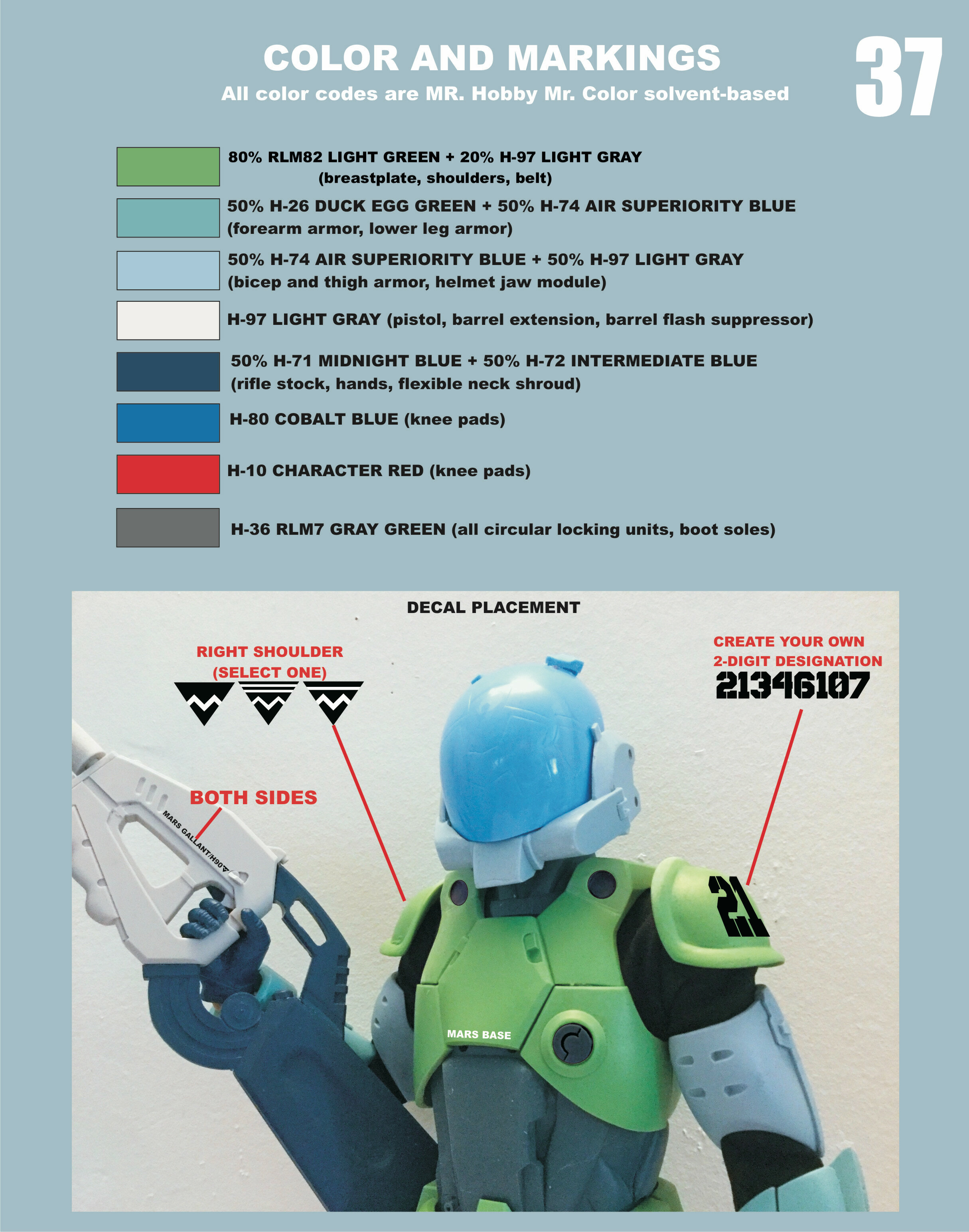
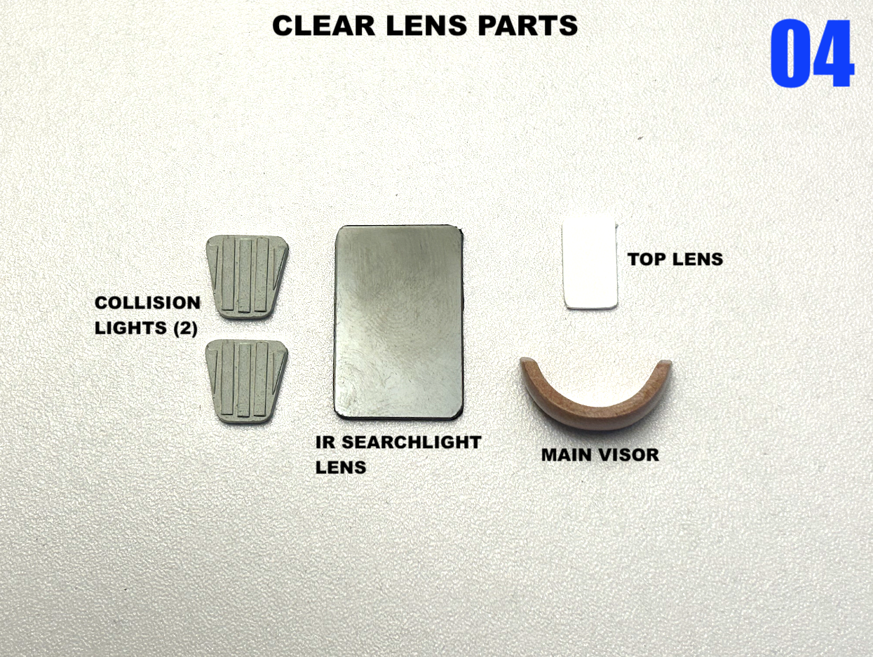
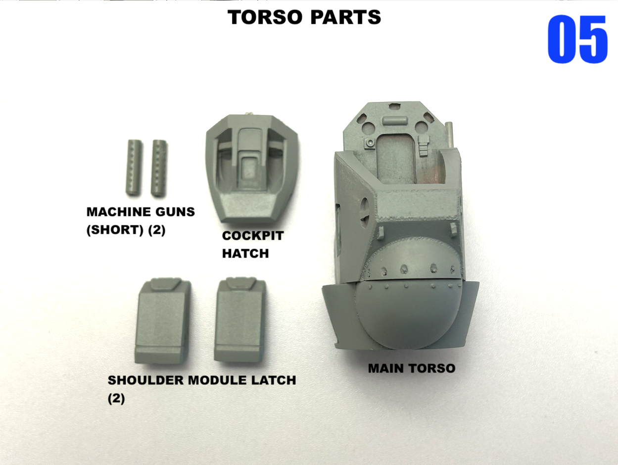
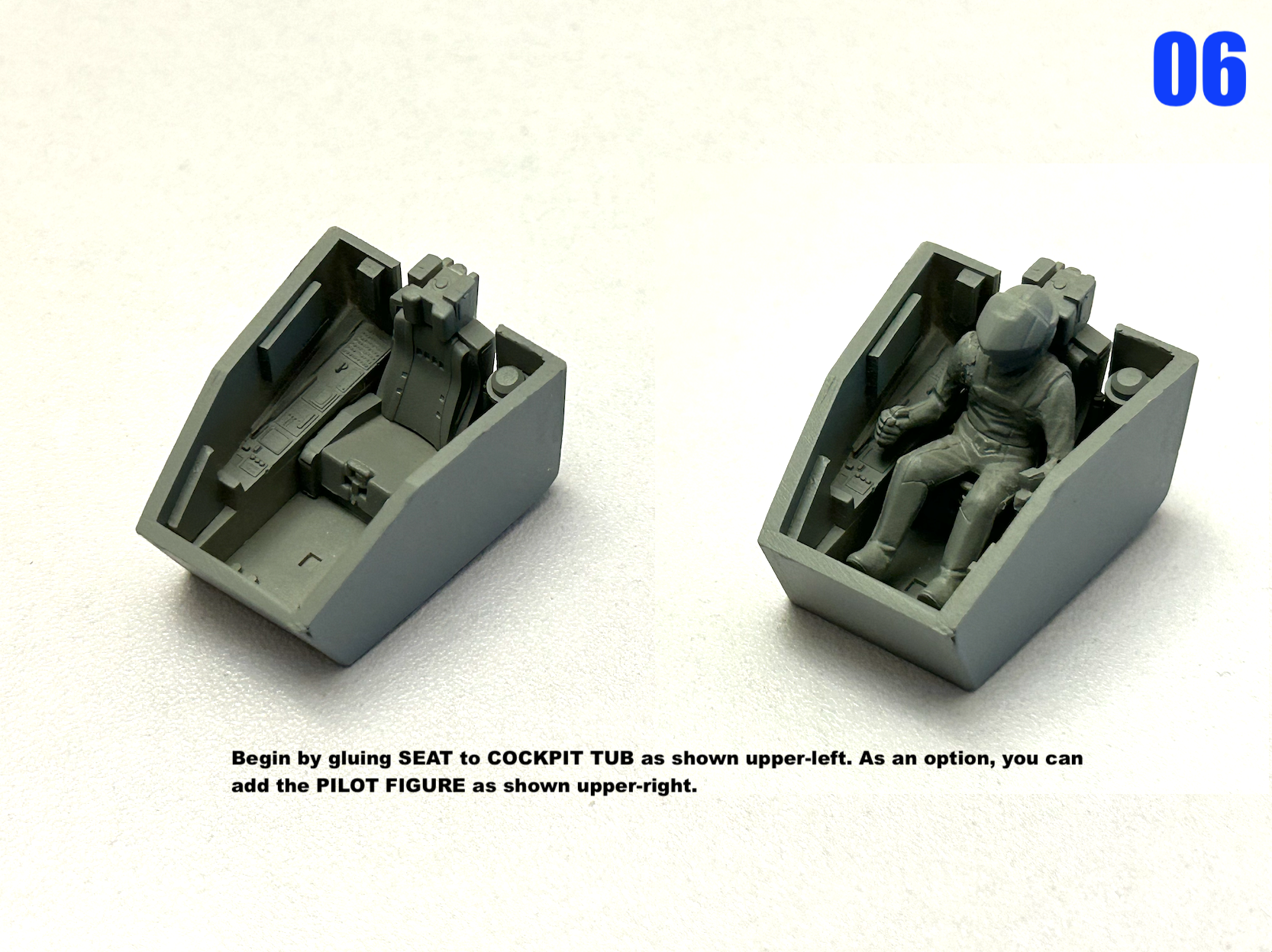
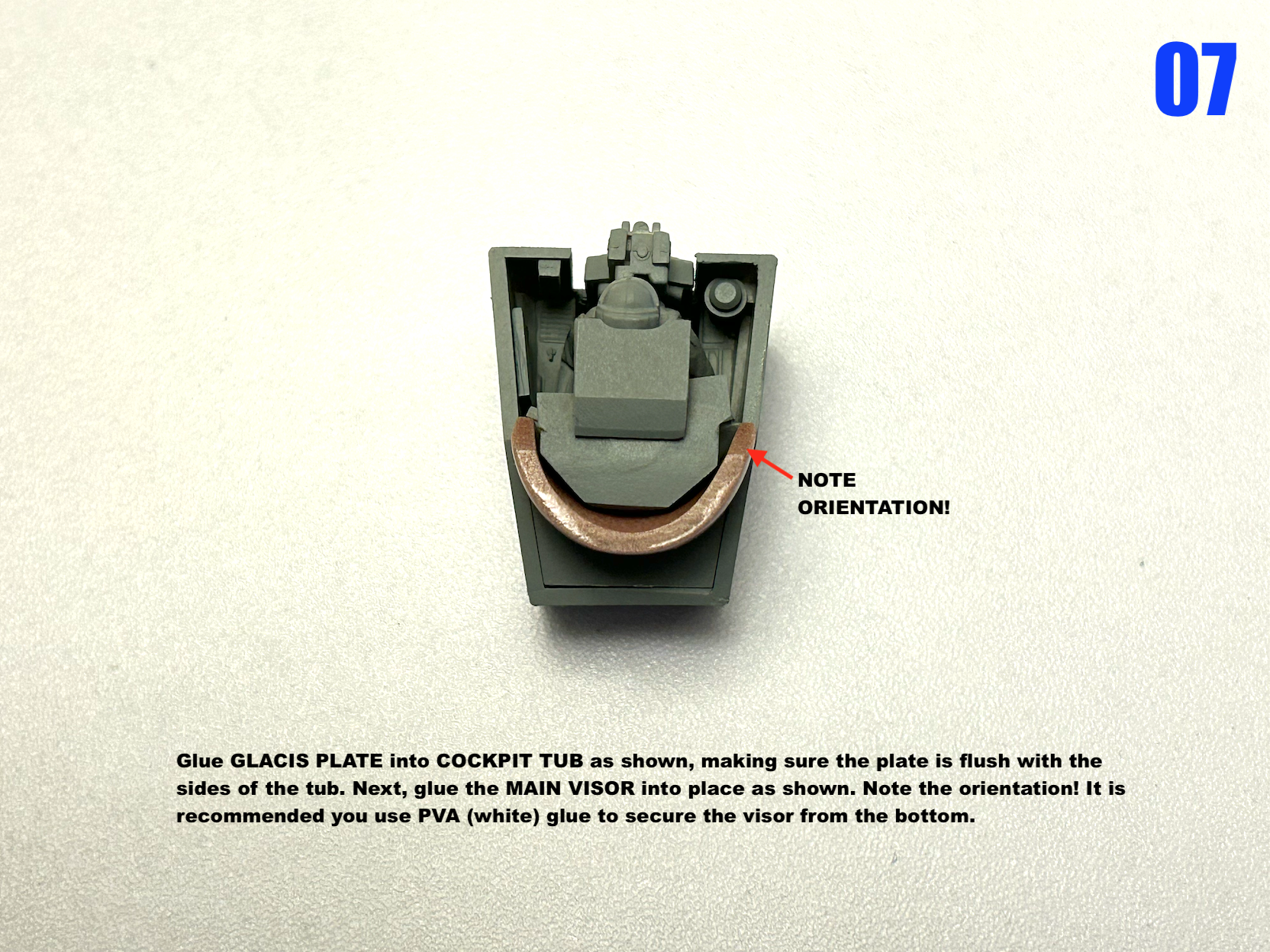
Hello, all. As Brett over at @return2kitform has been teasing over the last several weeks, I would like to announce that @moscatohobbymodels and Return 2 Kit Form are back, but in a slightly different way. As such, we would like to offer a re-issue of the massive 1/72 Tacticar Pod Graug kit, which I would be molding and casting myself. This is one of the largest kits I've mastered, and it hasn't been available since 2009. Because of the awkward design, this kit would feature certain load-bearing parts cast in high-strength polymer with inserts for optimal strength and rigidity. Other features include: -faithful cockpit detail -a seated pilot figure included -full color decals (not included in the original release.) In order for this project to go forward, we need a minimum of 10 orders. If you missed this kit when it was first released, the opportunity is before you now, 14 years later. Also, and this is VERY important: I will only producing enough kits to fill pre-orders. If you don't get in by the cutoff date of September 18, no other kits will be available. If you're interested, please send me a private message. Posting in the thread only will not be construed as interest. Base kit price w/o shipping is $510 cad. Countdown begins now!
-
Hey Ted, glad to see the kit arrived safely! I'm still waiting to see some completed Biopsycher pics.
-
I built that kit over 3 decades ago and even then, it was tedious! I ended up scratchbuilding almost half of it, so I know where you're going. Just by-the-by, the pilot's arms don't extend into the mecha arms, but are tightly huddled in the main chest cavity, hence the presence of knobs and controls in there.
-
No Love for Southern Cross?
captain america replied to blacklotus's topic in Anime or Science Fiction
The Battle Sniper mode is pretty decent, but the Clapper mode is an utter trainwreck. Understandable as it needs many minute adjustments to go from one to the other. -
Part 3 of 3
-
Part 2 of 3
-
Destructions!


-
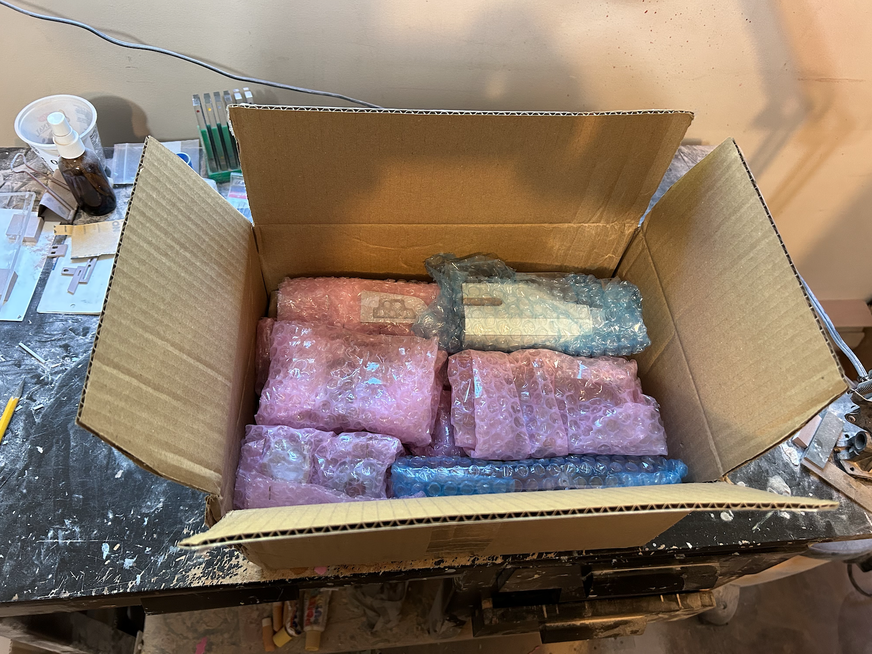
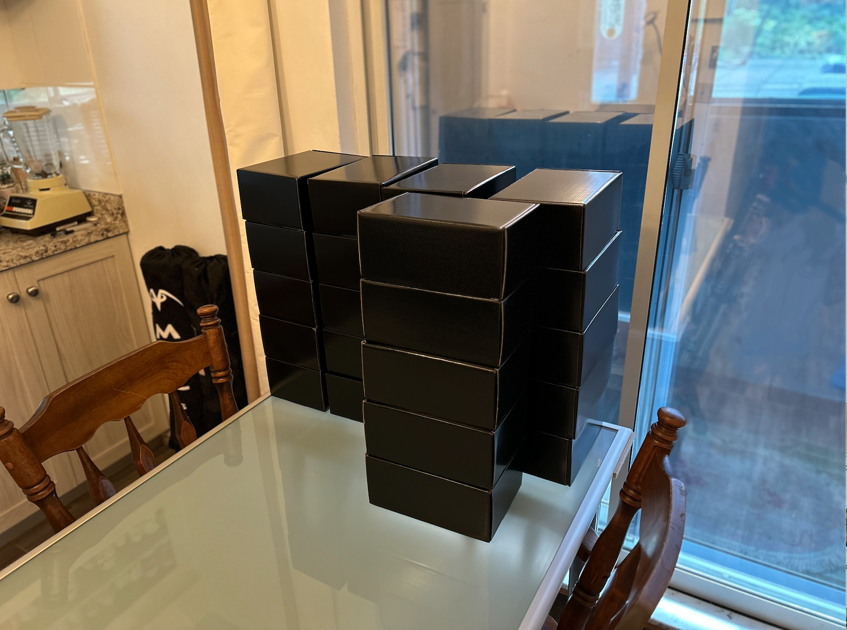
Quick Monday update: all kits are cast and being packaged. Decals should be here next week. I have two (2) final kits available; get them while you can! Now to finalize the instructions.
-
The aesthetics of the Alpha make me think of the old Robotech RPG illustrations by Long; they have a very American-comic-book style which doesn't suit the mecha. Most likely a 1/32 or 1/24 rendition pulled from the Sentinel 1/48 and then somehow mangled. And that fighter windscreen... What were they thinking?
