captain america
-
Posts
3550 -
Joined
-
Last visited
Content Type
Profiles
Forums
Events
Gallery
Everything posted by captain america
-
Hi Neptune. It all depends on if the demand is there. Before I get into sculpting it, I want to make sure that the people who ordered and paid for booster kits actually get them, and are satisfied with them. Once all this is settled, and if the requests are numerous enough, the launch vehicle will get done.
-
Last pic for now. Captain is exhausted... Needs sleep

-
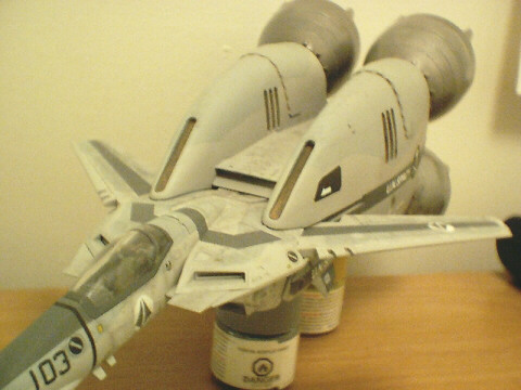
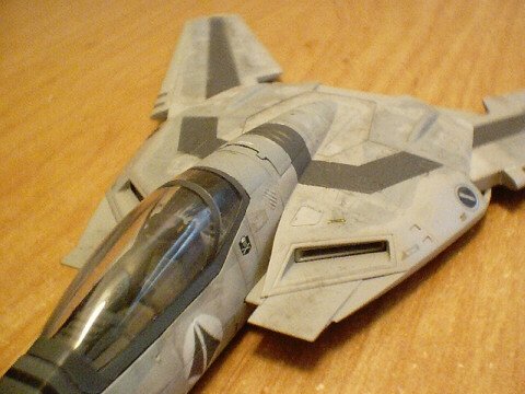
Overall shot.
-
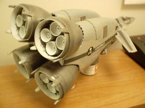
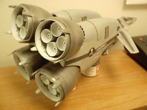
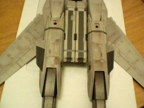
Backside, with all nozzles attached.
-
BOO! Teaser pics... It's almost finished.

-

NEW Official MPC Thread!!!
captain america replied to FRED THE FRENCH's topic in Anime or Science Fiction
I like posting this pic, just to annoy people
-
Legs still need to be permanently fastened, and some minor detailing.
-
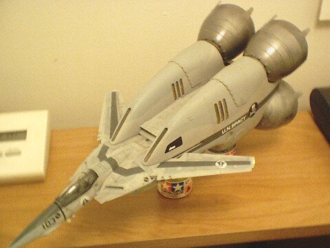
Hi Jesse! Your castings look absolutely FANTASTIC!!! I'm glad that things finally worked out after those first little mishaps, and I dare say that everyone wil benefit from these clean castings in the form of minimal cleanup. Truly first rate work, kudos! Hopefully I'll have pics of my own (almost completed) booster by next weekend; I just realised that I never truly posted any "finished" shots of the booster with all the nozzles attached. In the meantime, here are a couple more teaser pics of the Painted-up Valk... As you can see, I like my planes dirty
-
Hi Jardann. Thanks again for the pilot, I really appreciate it. I'm planning to keep the booster portion the same as the fighter color-wise, but I'll probably replace the UN kite with the Skull squadron logo on the booster... Just to give it a little extra oomph!
-
Last pic.
-
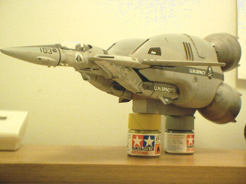
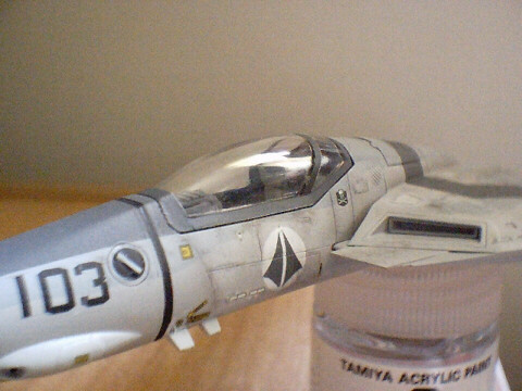
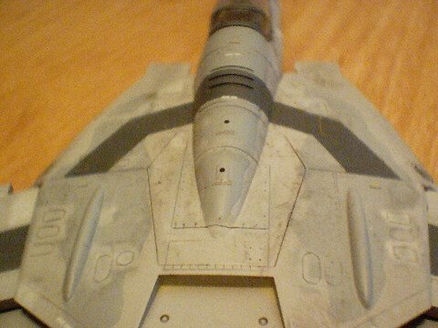
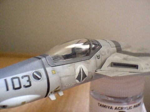
THe paint scheme was borrowed from current F-14 fighters, modified to still use the "Skull squadron" motif... But rendered with tactical greys au lieu of the usual black/white. Like the F-14, the VF-1 is a very complex aircraft, and in thus, would probably require a significant amount of maintenance; resulting in ground crew climbing all over the aircraft with dirty boots and greasy hands. This was actually quite easy to render with chalk pastels. Though it's hard to see, I also adorned a lot of the little acess panels with paint touch-ups, which are also common on current fighter aircraft. The impressive part is not that I was able to make paint touch-ups that small with an airbrush, but the fact that I was able to do them with a broken one( I litteraly had to re-solder the main body of my 'brush!) that also had a severely bent needle!
-
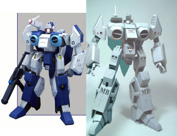
A very quick update... Just a few teaser pics of my chosen paint scheme for the buildup Valk + Booster. I've looked at Valkyries done up in a multitude of schemes, ranging from the original colors, to Minmay guard, to digital camo, and everything in between. While all these schemes are nice, in my mind, they didn't really convey the realism that I wanted to portray in my model. I simply wanted to make a Valk look as though it could be real, with real-world weathering. Essentially, to allow it to leap from the world of fiction, to looking almost feasible. The results are below.
-
NEW Official MPC Thread!!!
captain america replied to FRED THE FRENCH's topic in Anime or Science Fiction
Hi Felix. The tooling (dies) are usually owned by whoever paid to have them tooled. In 99% of the cases, that would be the toy company/liscensee (Toynami.) Toynami most probably own the tooling, so it's just a matter of taking it from the current factory to another; this actually happens a lot in manufacturing. However, taking the tooling to another manufacturer and then having them learn all the ins & outs of properly pigmenting the plastic, assembling things in a specific order, painting, etc, etc can be more of a headache than it's worth ( longer ramp-time.) The quality on subsequent releases will most probably be better (as was evident with the VF-1 series), simply because after you produce so many, you eventually work-out the little bugs during production and "get the hang of it." This is why I personally never buy first-run items. Early releases are ( as we've all seen) usually plagued with horrible QC. I really can't understand why lower numbers are worth "more", when the higher serial-number items are usually much better quality...It pays to wait, you see -
NEW Official MPC Thread!!!
captain america replied to FRED THE FRENCH's topic in Anime or Science Fiction
Hi Felix. Absolutely true. The good thing is, if you take a typical HK toy manufacturers catalog (it's litterally the size of a LARGE phone book) and are willing to make a few calls and request a few samples, they could most certainly find a manufacturer that could deliver the quality at a reasonnable price and deadline; they really DO have the pick-of-the-litter in that respect The tooling portion of the toy actually seems reasonnably-well executed, it's really the carelessness in the assembly and painting that ruins the toy's potential. -
NEW Official MPC Thread!!!
captain america replied to FRED THE FRENCH's topic in Anime or Science Fiction
JS: I couldn't have put it better myself. As it turns out, I got to play with an Alpha POS just today, as a retailer/buddy of mine was able to put his hands on some. My own impression, as someone who works in the toy industry, is that the toy was done on the cheap(and I mean cheap!) I wouldn't say that Toynami were trying to do TOO much with the engineering, they simply let the lowest-bidder (manufacturer) run amock and unsupervised throughout production. As a rule of thumb, manufacturers in china want to get through production runs as quickly as possible; they don't give a rat's a$$ about quality; they just want to get the stuff out as fast as possible, get paid, and get some other banal item out just as quickly, etc. The plant managers "pocket" most of the money, and hire the absolute cheapest workers they can. They'll litterally hire someone wandering aimlessly at a train station. "You, you, and you. Come with me, I have work for you" bellows the foreman on his quest for cheap labor. You then have assembly line workers who, just the day before, were janitors, now building toys on an assembly line for the first time....Aaaah, the beauty of cheap, commie labor In the end, the factories do this because it's in their best interest to make money. The true blame lies with Toynami for approving the production samples, and/or most probably NOT adequately supervising the production of the merchandise they paid to have done. You REALLY have to watch the factories like hawks, or they'll turn out garbage by the truckload the second your back is turned... And just as quickly sell extra units on the docks for cash to a shady guy in a pickup truck. Why do you think there's such a flood of "cheap" toys coming out of HK? Alas, whether Toynami will keep making money with their flawed business plan depends on how much longer people are willing to pay top dollar for sub-standard merchandise, It may work for now, but I have a feeling that it'll run its course pretty fast. -
http://www.macrossworld.com/macross/mwat/j...scato/valk2.jpg
-
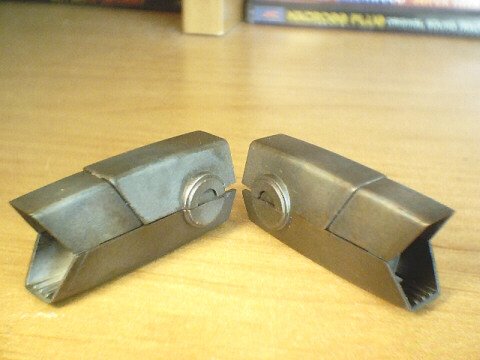
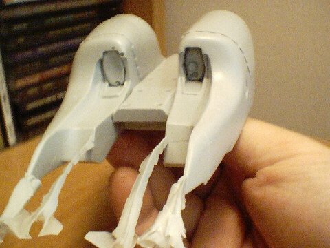
Here are the feet/exhaust nozzles. The camera won't seem to pick-up the wonderfully-subtle heat-discoloration I painted onto the Testots Metalizer finish. They essentially have a "mottling" effect painted on with clear blue, yellow and red, thinned with rubbing alcohol. I actually have more parts done, but nothing worthy of camera-time, so I'll save the pics for when things get interesting again.
-
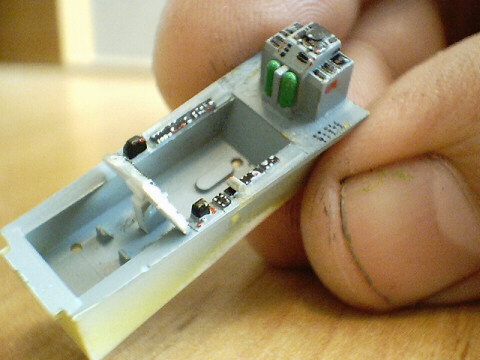
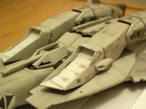
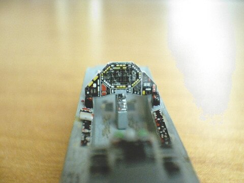
The assembled cockpit. Sadly, a lot of the nice detail will be obscured when it's all encased within the fuselage.

-
The tub from the pilot's view. The cockpit displays are the kit decal, but in stead of using it as a whole piece, which didn't look right, I cut it out into placards and mounted them individually. I then coated them with some FUTURE floor wax to make them shiny... Essentially a "glass" cockpit. Also, the tub was initially painted in Zinc Chromate yellow-green, and then overcoated with grey. I then scraped off a bit of the gray in the footwells & on the corners of the consoles to make the tub look like it's seen its fair share of action.
-
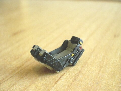
Pic 2: cockpit tub. More or less stock, but after painting it initially, I was left rather flat by the bare side consoles, so I pulled out my Perfect Memory, and sure enough, there are supposed to be placards in there, so I just made some out of styrene and added a few little switches & buttons with paint.

-
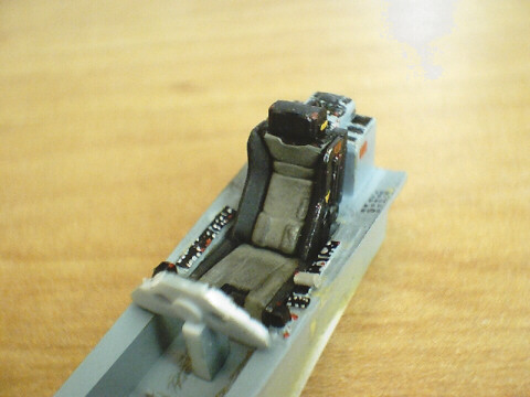
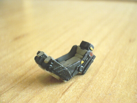
Hi guys, update time again. Basically, this will be a catalogue of highlights involving the actual Valk/Booster model grand prize build-up. WM cheng already did a fabulous step-by-step article on the VF-1, so I won't bore you with the same ol' "glue part A to B, and putty". Rather, I'll just hit the highlights. Pic one is of the ejection seat. Painted up in a more real-world military scheme of black frame & olive cushion. The cushion was made to look worn with some black/brown chalk pastel, and the frame recieved a few little nicks of silver to simulate chipped paint. I also added a few hand-painted warning symbols.
-
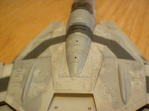
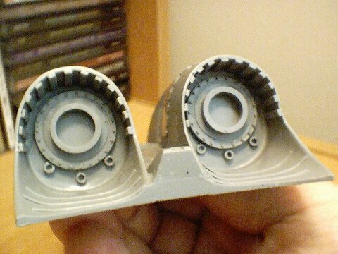
Last pic. Lower fuselage, rear view. Very nice detail capture.
-
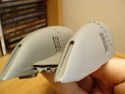
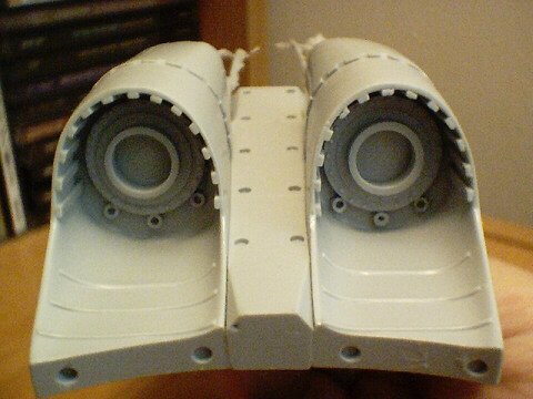
Lower fuselage, foreward view. This is about the only part I was a bit disappointed with. As you can see in the pic, the foot holes have extra resin in them. Though these can easily be ground-out and sanded, I also took some steps to correct this in the molding process on Jesse's end; basically re-positioning the part to better release entrapped air in the mold material. The part is a bit more complex to mold than it appears, as it has detailed indentations fore and aft. However, this should be remedied in the actual production parts.
-
Same part, rear view. Excellent casting
-
Upper fuselage. The flash in the pic looks worse than it really is; you can strip it right off with a sharp knife. The airflow grill holes were casting-up a little bit rougher than I care for, so before I sent the masters to Jesse for casting, I re-worked the part slightly to eliminate that problem.