wm cheng
-
Posts
4296 -
Joined
-
Last visited
Content Type
Profiles
Forums
Events
Gallery
Everything posted by wm cheng
-
If you scrub with a old used toothbrush and comet, you will get into all the nooks and crannies.
-
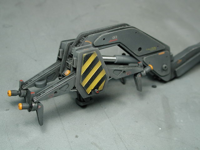
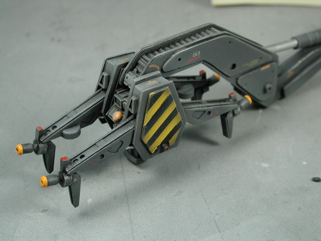
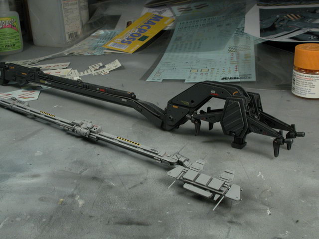
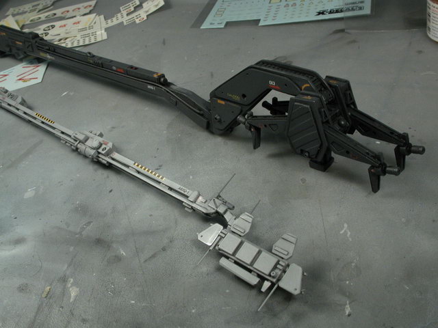
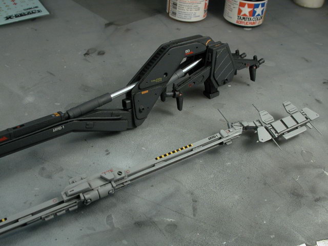
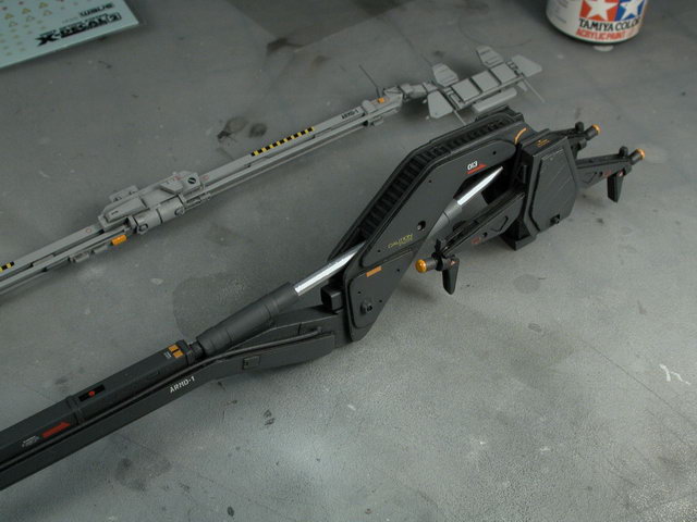
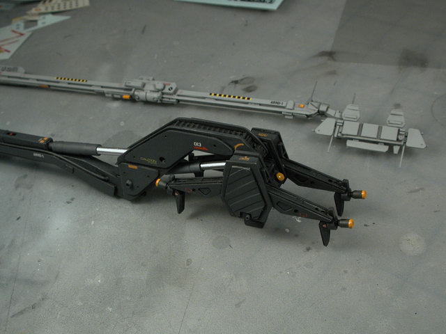
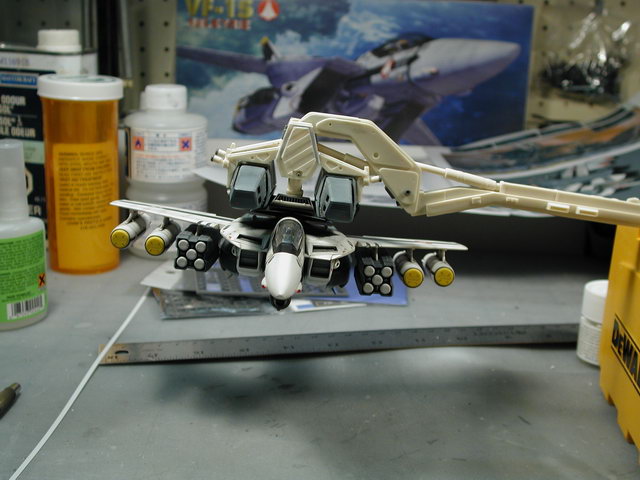
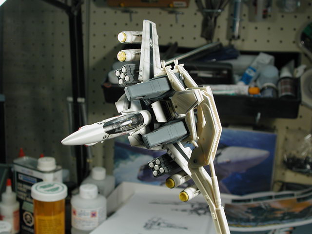
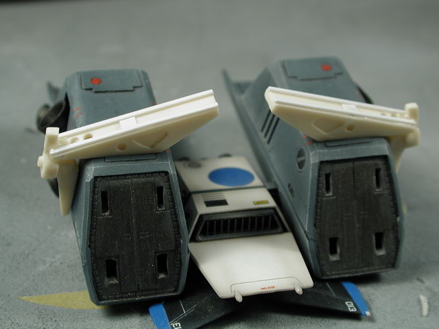
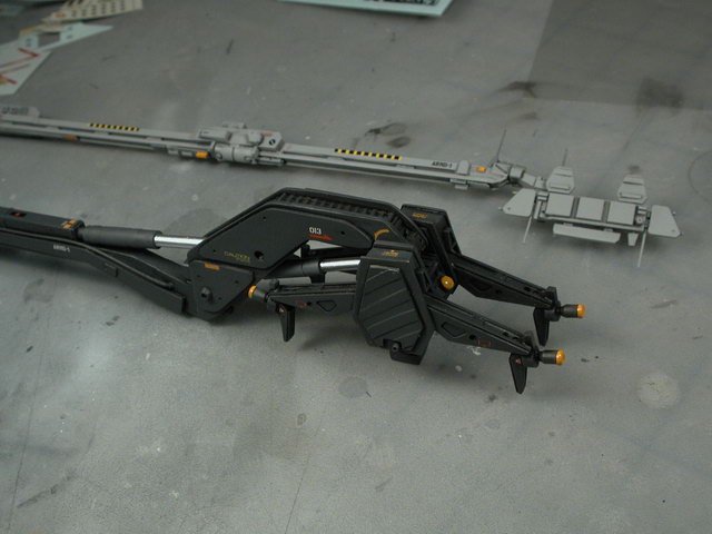
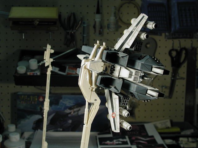
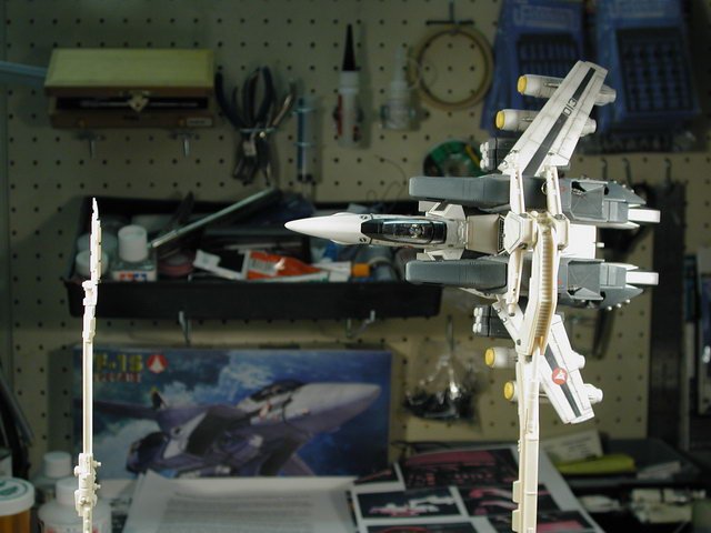
Final shot of the night for now... I added the hydraulic actuator/cylinder between the wrist and claw portion - again I used the Tamiya marker for the actuator and Neutra Grey for the cylinder. I crazy glued it in. I left the main large hydraulic actuator/cylinder between the wrist and arm off for now - I need to let the Silver Tamiya marker dry first. Its pretty close to finishing, I just need to add all those hoses and wires to connect up the arm and the signal piece as well. Lastly, I'll finish the base, but that will be in the end. Enjoy...
-
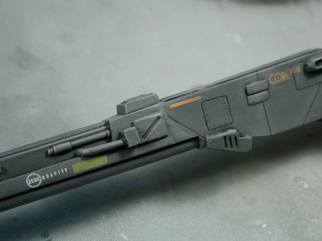
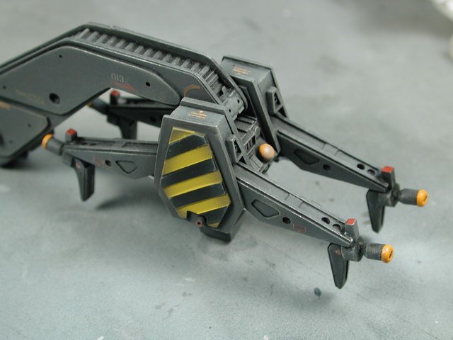
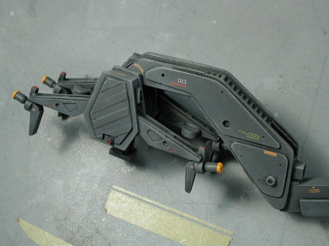
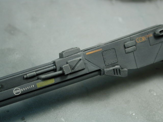
Oh, at this point, I masked the big yellow and black warning area - and sprayed. I actually took off that little detail in the lower centre with he red dot on it, since it interfered with the masking - and added it back in after I removed the masking. I would suggest leaving off until the yellow and black stripes are done next time. I then went around the edges of the warning area with a thin light spray of dark grey to dirty it up a bit (it was too bright, clean and new) and work it into the arm so that it didn't stand out too much. I also dry brushed a little sky grey around the edges to show this area was worn as well.

-
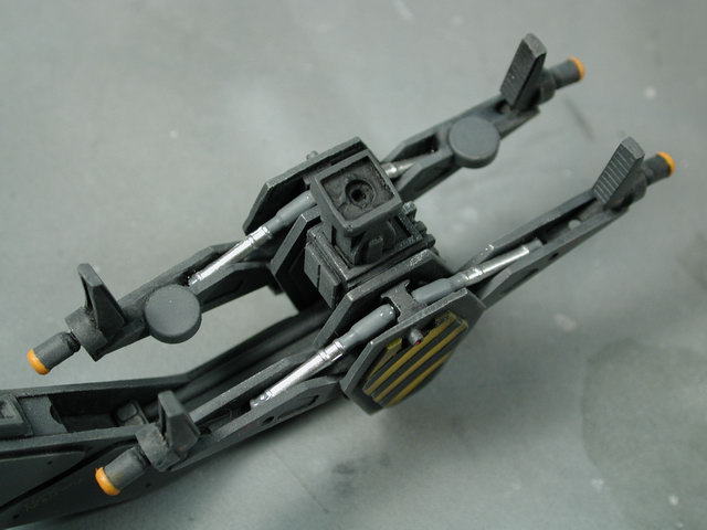
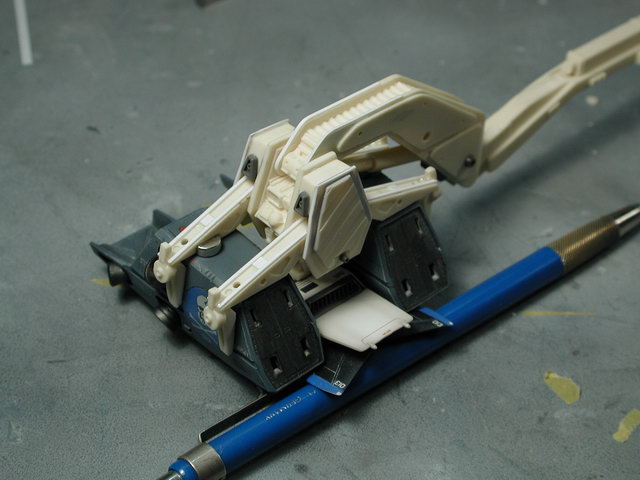
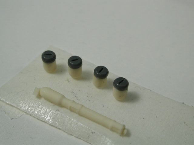
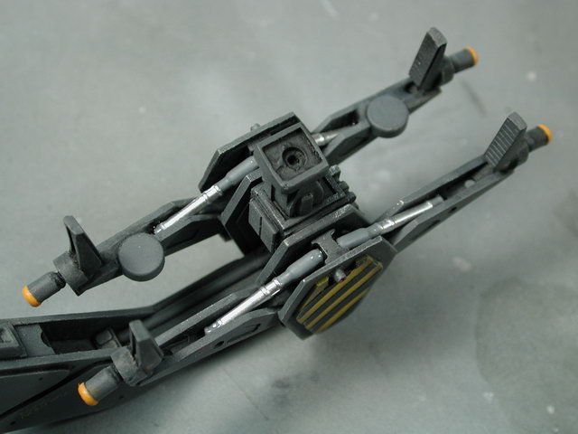
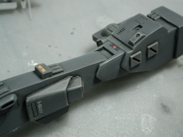
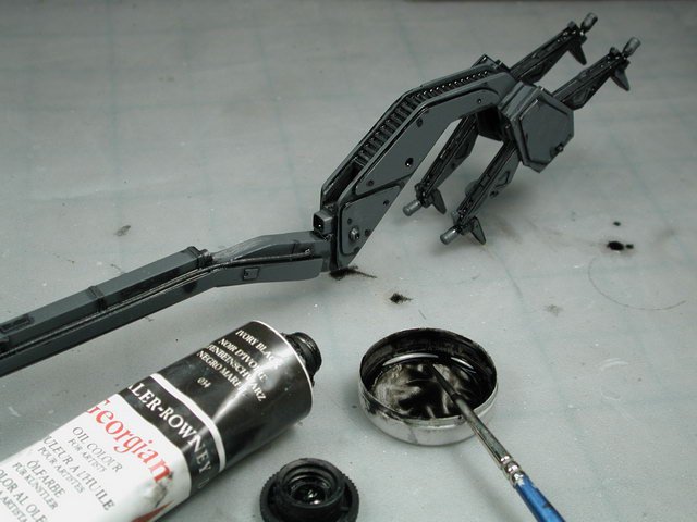
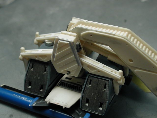
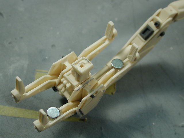
Not to forget, I added the four little hydraulic actuators underneath the claw fingers. I painted a portion of them with the Tamiya chrome marker (I don't know about the Gundam markers - I haven't tried them yet) and the rest with Neutral Grey so that they would stand out against the dark grey fingers. I also had to trim a bit of them off on the rear arms since the epoxy from glueing the magnets got into the way a little - but when you flip it over, you can't tell. Just a hint of metal mechanism - very cool.
-
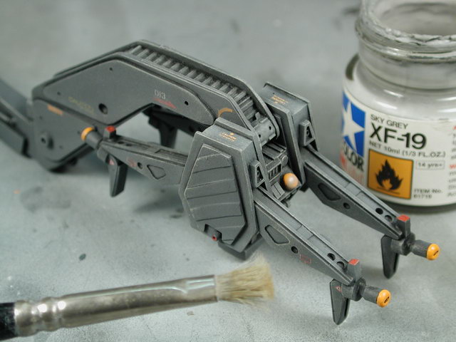
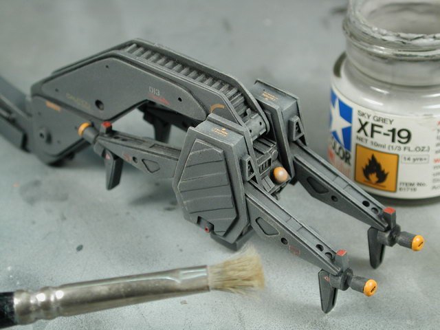
On to a favourite part of mine which I rarely get to do on a Macross model - dry brushing. It is usually a technique quite common in tank modelling. Together with the oil wash which picks out the low lying recessed details, the dry brushing will pick out the opposite highpoints in the molding - it will look like worn metal when its done. I usually find a flat edged brush that is fairly stiff (I used an old watercolour brush with synthetic bristles) - this is the only use for this brush because the process is fairly rough on the brush and will ruin it for other use. It can be done with white (which I did for the fast packs on the Super Valkyrie) or I'm using Sky Grey in this instance. You dip the brush into the paint, then take it out and using a paper towel, remove most of all the paint off the brush. Then take a scrap piece and start to work the brush around all the raised edges of the model - what little paint is left on the brush (the brush should be dry to the touch - hence the name dry brushing) should catch on the raised bits of detail. You will need to go over areas a few times to build up a lightening of the edges. It works best around the edges of panels and any highpoints in the molding. I would do this first with the grey, then I do it again with a bit of silver, but only hitting certain areas, so that certain edges gives a glint of silver as thought the paint has scrapped off. If done subtly it should give the impression that there's metal underneath the paint (hard to capture on the picture).
-
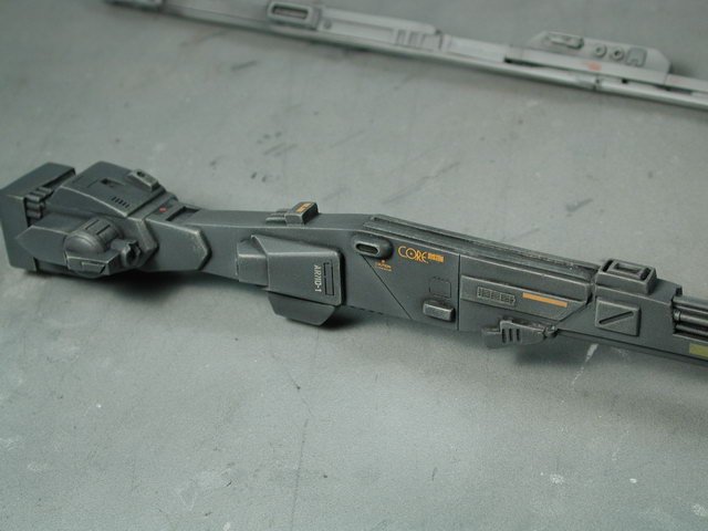
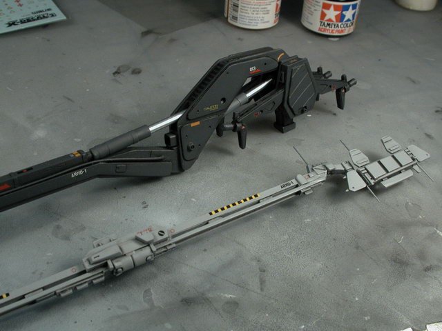
I sprayed the entire thing down with a clear coat of Model Master Acryl flat finish to seal in the decals (helps blend the decals in with the same finish as the paint) and the oil wash. Plus dry brushing works best on flat finishes. You'll also notice that the flat finish lightens the entire arm up quite a bit.

-
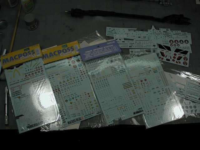
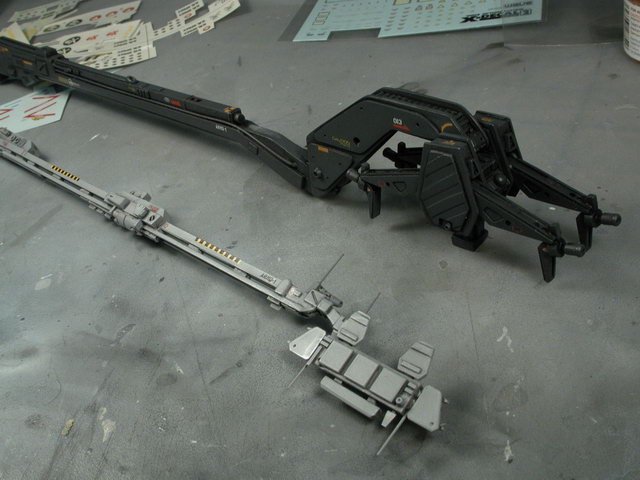
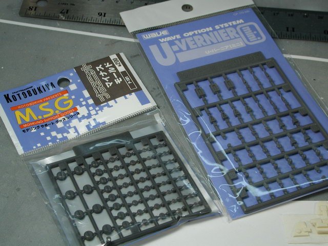
YAY! decal time... I have a huge collection of leftover decals from old kits spanning 20 yrs from when I was a kid. I even knew enough to save the decals to the kits I built when I was too young to paint and apply decals! Anal eh?! But Macross has a certain sensibility that I wanted to maintain - I didn't want it too look to military, but it needs a certain air of japanimation too. I thought this was a great opportunity to use my old leftover bits from my other Hasegawa kits and these great Wave Option decal sets I ordered from HLJ a few years ago. I highly recommend them - two are Macross Option decals, and two are just Misc. Option decals (more Gundam like). http://www.hlj.com/hljlist2/?Maker1=WAV&Ma...eCode=Sci&Dis=2 They contain fantastic stenciling and various sci-fi like warnings "Zero Gravity" and graphics. I've dry fitted some of the hydraulic actuators in some of the photos - I love how the Tamiya marker chrome makes it look like real metal especially contrasted next to a flat grey finished hydraulic cylinder. The key to some of the graphic stenciling (IMHO) is to position them next to something, some kind of feature on the arm - so that they are pointing to, or warning some aspect of the machinery. It lends a air of credibility to the what's being applied. The semi-gloss clear coat allows the decals to lay flat against the surfaces without the silvering that can appear on dark backgrounds. When I seal everything in with a flat finish clear coat, it will blend the decals into the finish of the arm more. THen I will dry brush and airbrush a lighter grey over them to tie them into the arm at the end.


-
So correcting the signal was a little more involved than I thought. First I filled in the hole I drilled in the base with crazy glue. I let that set before I drill a new hole in the location appropriate to swinging the arm around 180 degrees. Then I detached the signal arm from the signal assembly - carefully... but I still broke the attachment elbow, so pieces in the back of the signal assembly and two of the signal paddles before I was able to extract the signal I scraped away some paint to where the elbow will attach to the signal (since I wanted the crazy glue to attach to the resin and not the paint). I also changed the location of the antenna to the lower signal paddle (as shown in the lineart). I then stuck a piece of gak from one of those Wave Option parts on the back of the connection elbow to hide the piece that broke off.
-
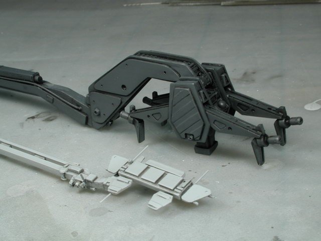
Thanks for bringing the signal arm orientation to my attention I have since corrected it, unfortunately not before I did my oil wash to pick out the recessed details. So I applied the artist oil wash thinned down with low odour varsol the same as my other styrene plastic kits, except I used pure black on the dark grey main arm and a medium grey wash for the lighter grey signal arm. I let the mixture dry for a few hours before I wiped the excess off with a paper towel - leaving the dark wash in the low-lying recessed areas. The highpoints will be highlit with a lighter grey dry brush technique after I apply a clearcoat of flat finish over the decals.
-
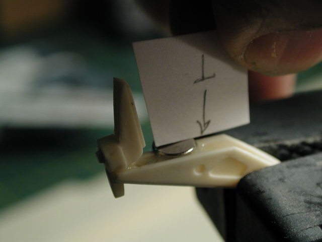
DAMN!! argh... You're right!!... ok.. calm down now - lets see how I'm going to go about this. Thanks RTHK! I guess I could try to break it at the joint between the signal arm and signal, then flip the arm around and turn the signal upside down. But I've drilled the hole in the base already for the arm (and the hole isn't right in the centre for me to just swivel the arm around) Ok, for those using this thread as instructions... I've goofed, don't mount the signal the way I have. Don't have time to work on it today - but will think about it.
-
Hey RTHK, can you be a little more specific... I know there are a few different shapes to the top and bottom paddles shown in the various lineart.
-
I "think" I will have time someday... but its also because I missed out on certain kits in my youth, either I wasn't around or too poor to buy it, that I've always regretted it. Now, if I have the means, I'll buy even if I don't have the time right now - thinking I may have the time later, or when I retire. When I have the time, these kits may not be so readily available anymore. It gives me a nice feeling to know "I have it" it prevents me from obsessing over it. I don't collect to see them raise in value - my macross collection is too important to me to ever sell, it represents a good part of my childhood and my best friend (who is dead now - I have inherited his collection, which means I have double originals of everything now, but would never sell them - they mean too much to me). Although, my justification to my wife is that its a good investment but I think I've come to realize that I won't ever really sell any of it. Its just so nice to have something from your childhood not be forgotten, infact, how many things from the 80s are seeing companies invest in new toys or models 20 yrs later!
-
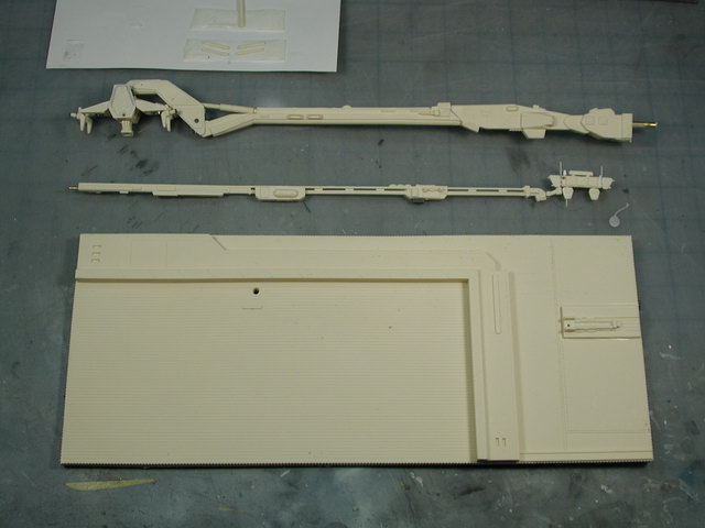
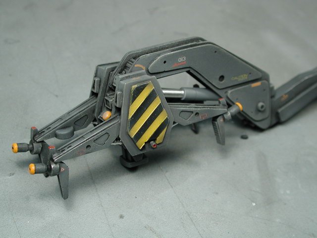
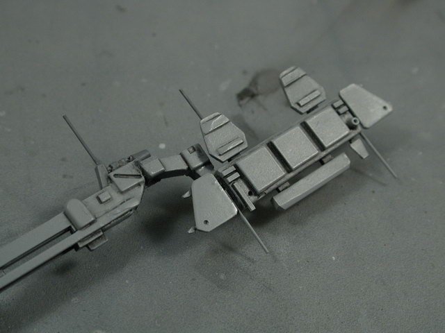
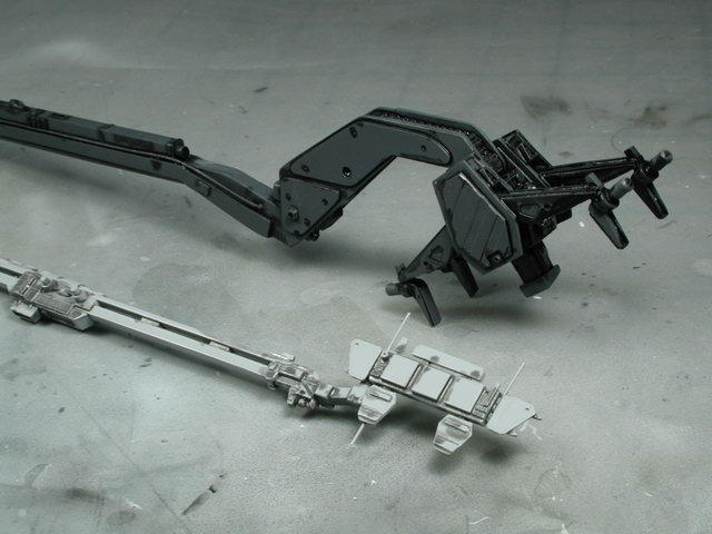
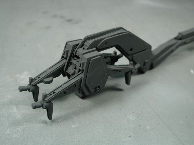
OK, so now the kit looks like so. And is ready for painting (finally!) one of the parts I've been looking forward to. I love the Tamiya chrome markers - I haven't really found anything that beats it for shinyness yet. I paint all the hydraulic actuators at this point with the chrome marker, then I'll handpaint the hydraulic cylinders afterwards. Here's a couple of shots of the first basecoat. I'm using Tamiya dark grey as the main arm's base coat. I was so looking forward to painting that I forgot to spray a primer first on the resin model. One should always spray primer onto resin kits first - that being said, I forgot, and the grey turned out excellent, so I'll skip this step (but its not recommended) I love how the grey unifies everything so all the add-on bits and modifications dissappears into a cohesive whole! The signal tower only has the primer grey on it - I am using the Alclad pre-mixed laquer primer - I love this stuff and its so easy to use (its just a little expensive). But I think this grey is the proper colour for the signal arm anyways - so I'll just clear coat it as it is. I am clear coating all of this in the Model Master Acryl semi-gloss so that the oil wash will not stain the flat finish paint that I've used. The next step will be a black oil wash to pick out all the recessed details and give it more depth. Now, I've got to let the basement air out a bit - with the primer laquers and clear-coats, its just hangs in the air. I still need to get a spray booth - at least some kind of vent to vent all the crap outside. Thank god I have my resparator - remember you must use an organic filter in the resparator. Wife's coming home soon... gotta make dinner (maybe I might get to the oil wash tonight - lets hope, but it's "Lost" on tonight - and someone dies )


-
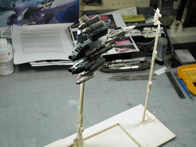
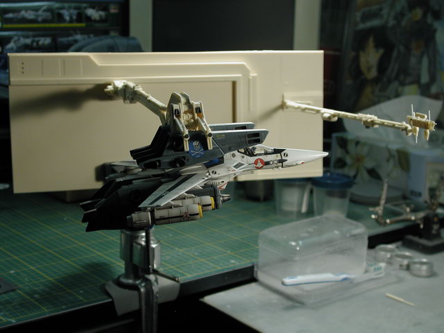
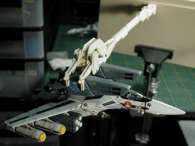
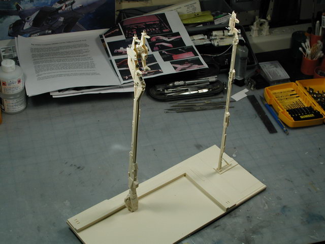
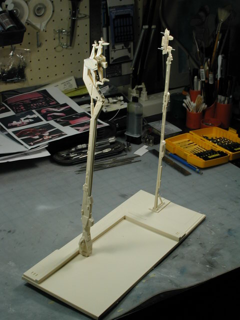
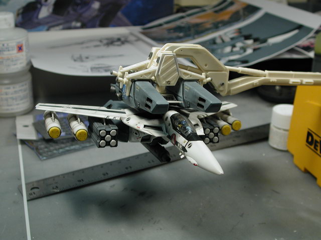
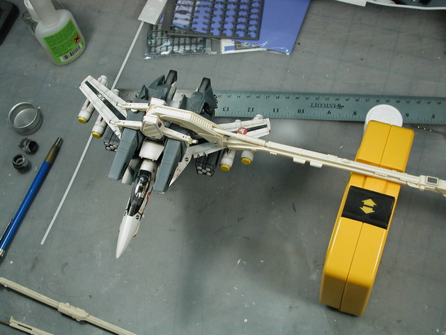
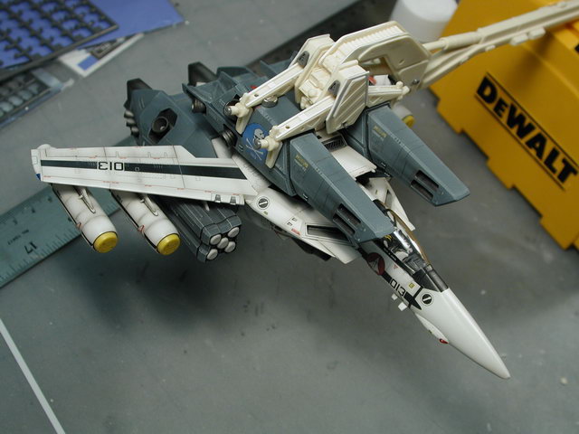
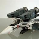
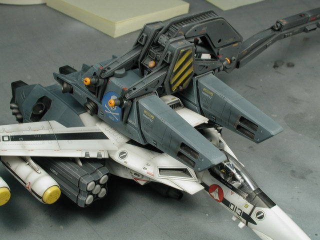
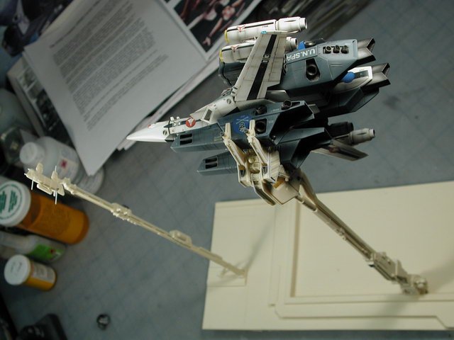
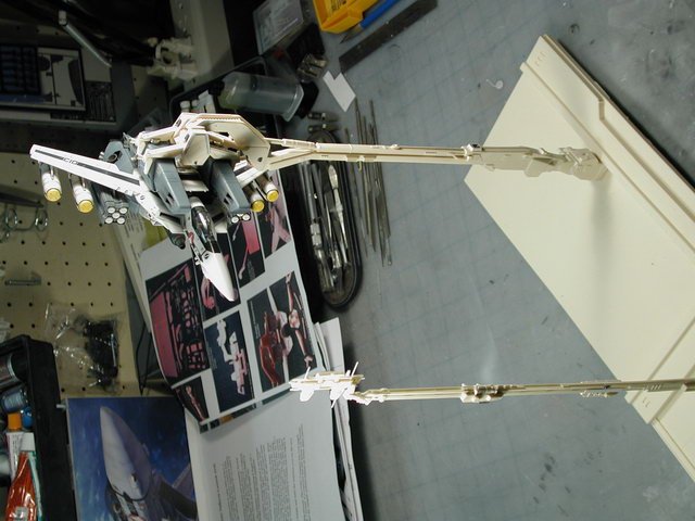
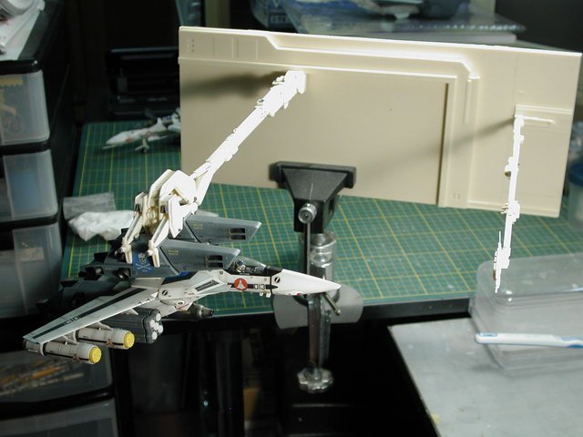
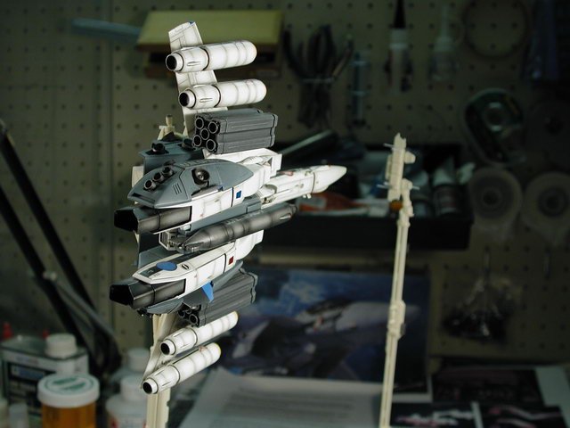
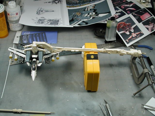
OK, here's a series of shots with the Valkyrie in place! I loved the look so much I kinda got carried away with the number of pictures Its really easy to remove the Valkyrie - just pivot it backwards while holding onto the claw, it levers the magnets apart - but when its on - its really strong (so my worries about the magnets are finally put to rest). Enjoy... hmm... the balljointed vise is kinda cool to mount the entire display to - I wonder if I can find a smaller version somewhere.


-
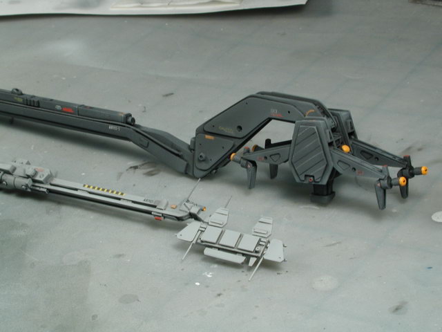
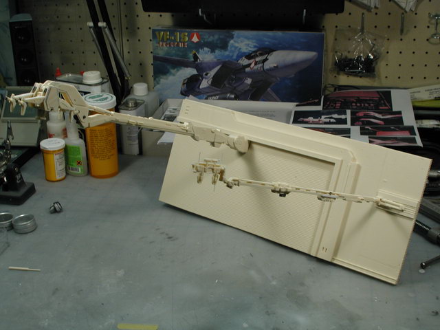
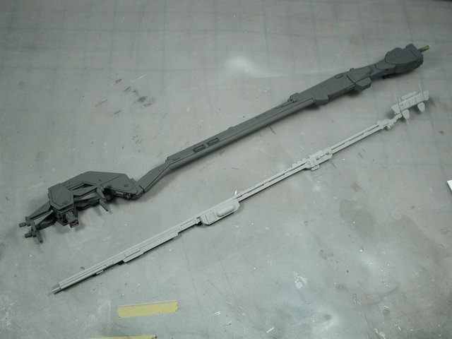
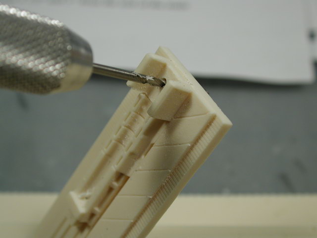
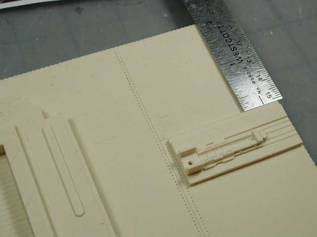
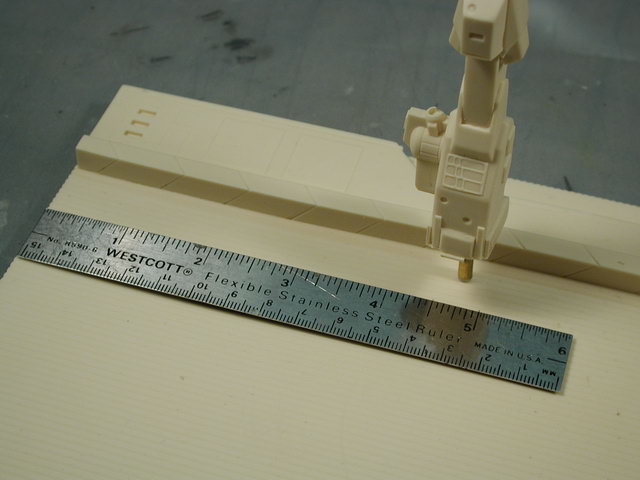
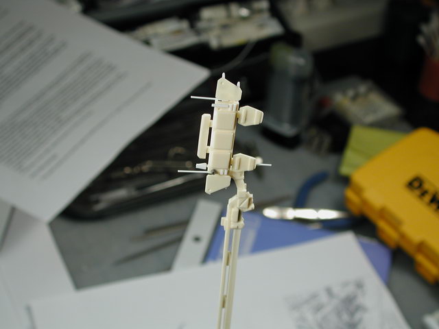
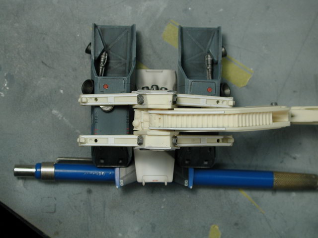
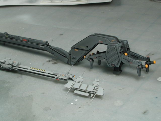
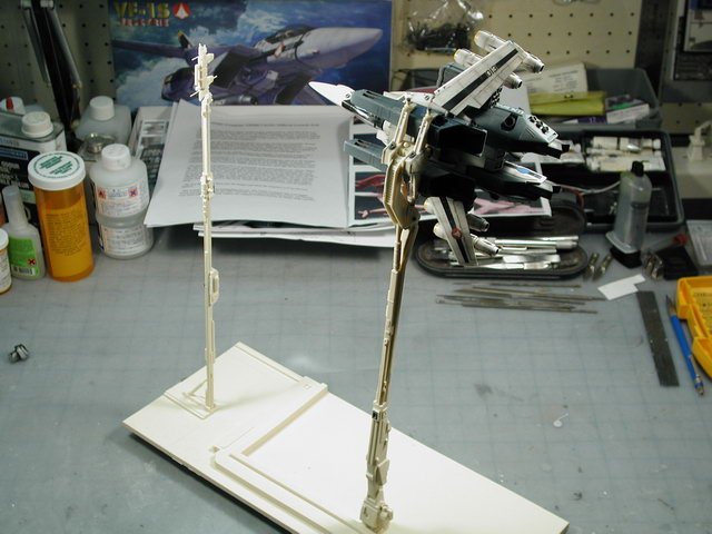
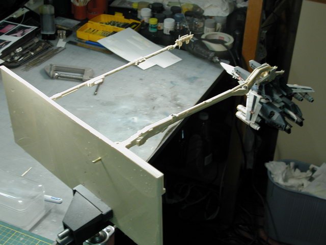
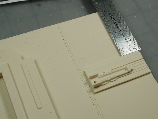
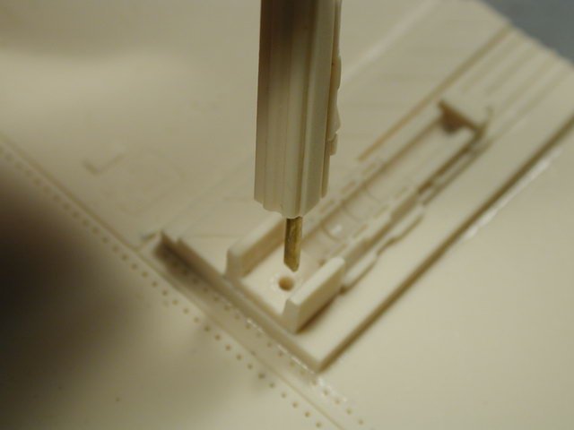
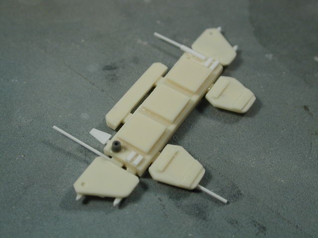
I also started looking at mounting on the base now (although I want to concentrate on finishing the arms first). I drilled a 1/16" hole in the signal arm base and proceeded to measure out the distance 2" as indicated by the instructions. Although I moved it down a little bit to expose the fine panel line Gundamhead scribed on the surface. I also measured 5" in from the edge for the main arm and proceeded to drill a slightly smaller hole 9/64" so that the main brass tube will friction fit into the resin base. I left the excess tube poking out the back for now - but was thinking that I will eventually cut it down and anchor it in place with a screw through into the tube backed by a large washer to more evenly distribute the torque at the mounting hole. All these pictures show everything friction fitted (I don't want to glue anything in until I finish painting) its always easier to paint in separate pieces.


-
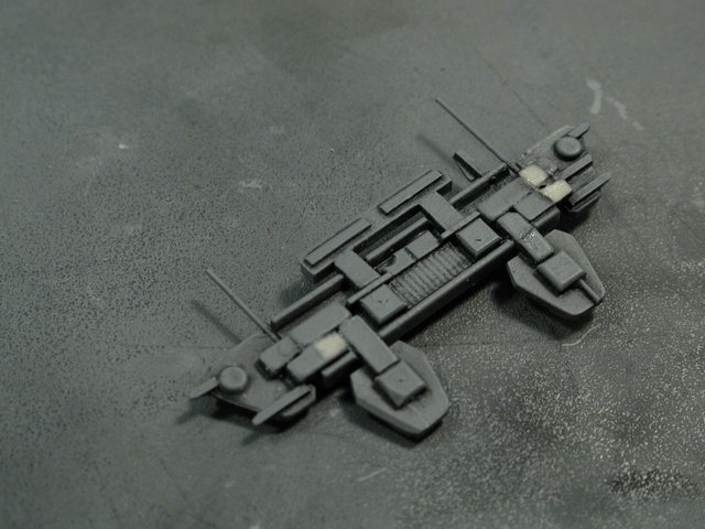
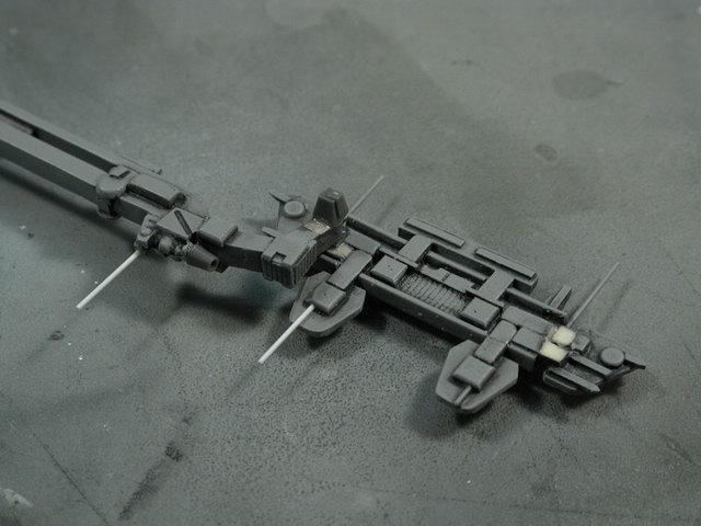
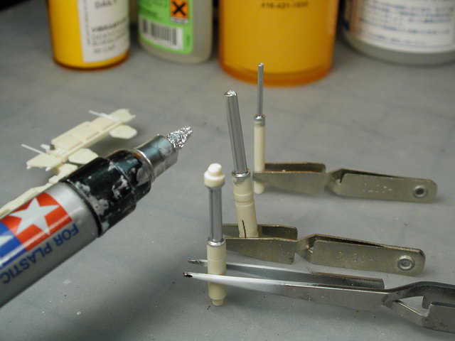
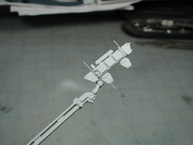
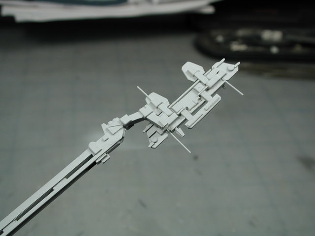
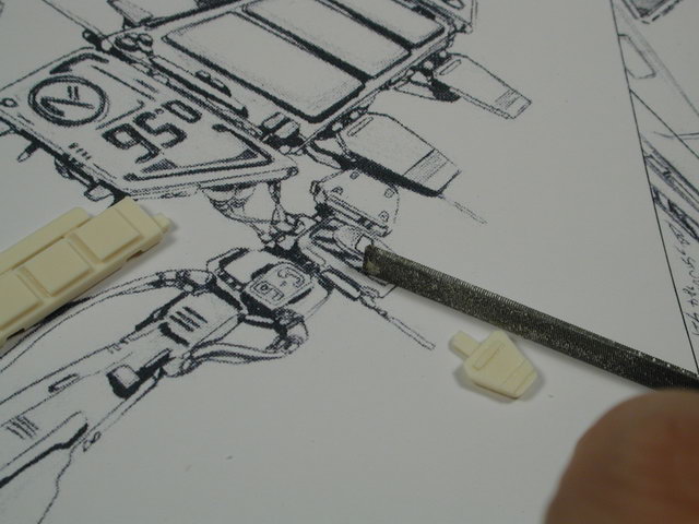
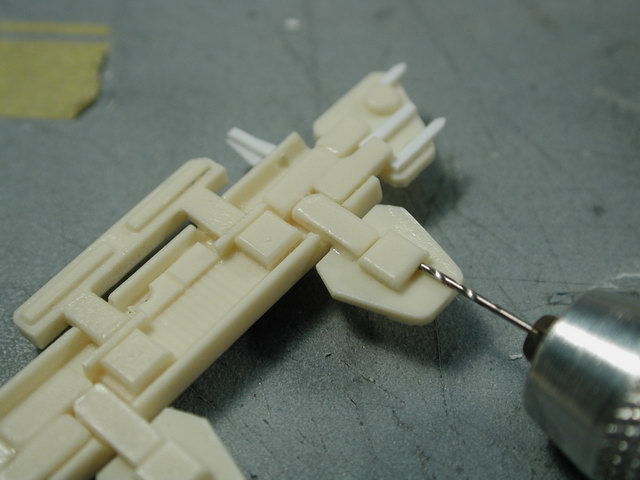
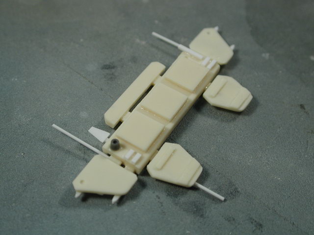
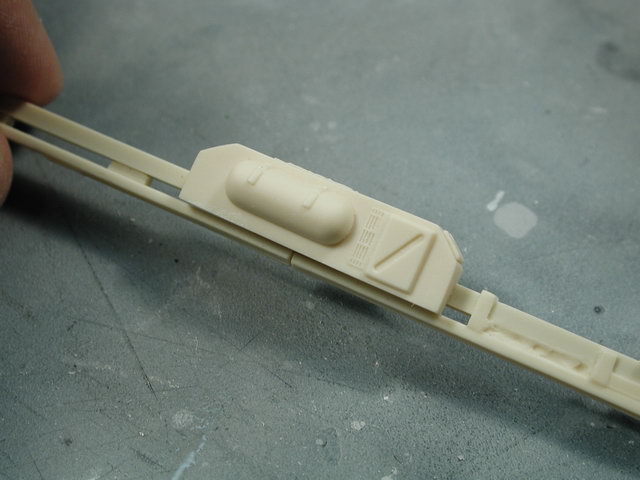
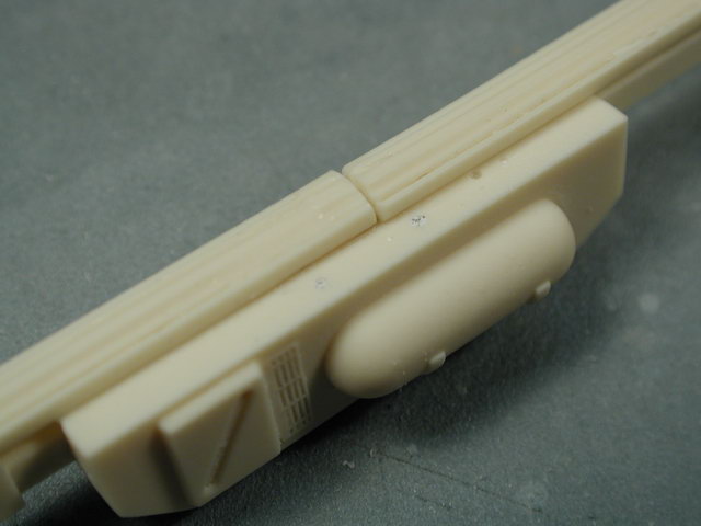
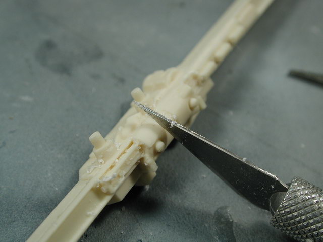
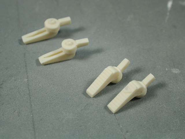
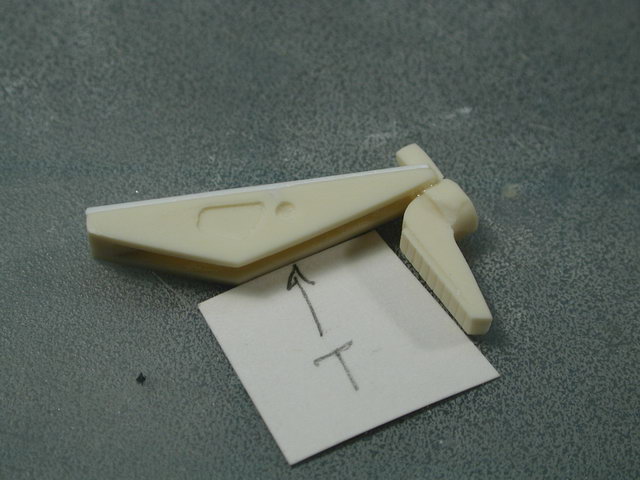
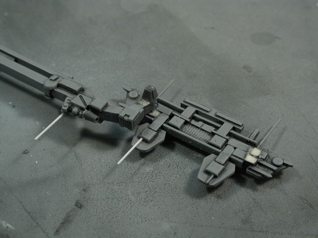
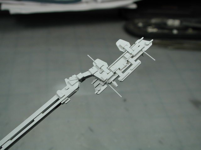
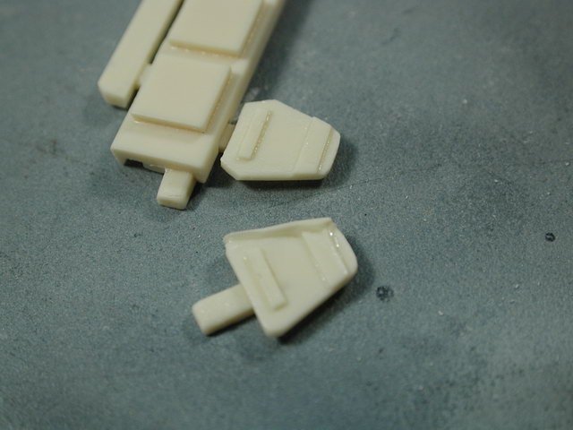
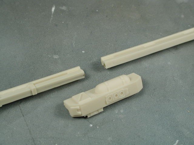
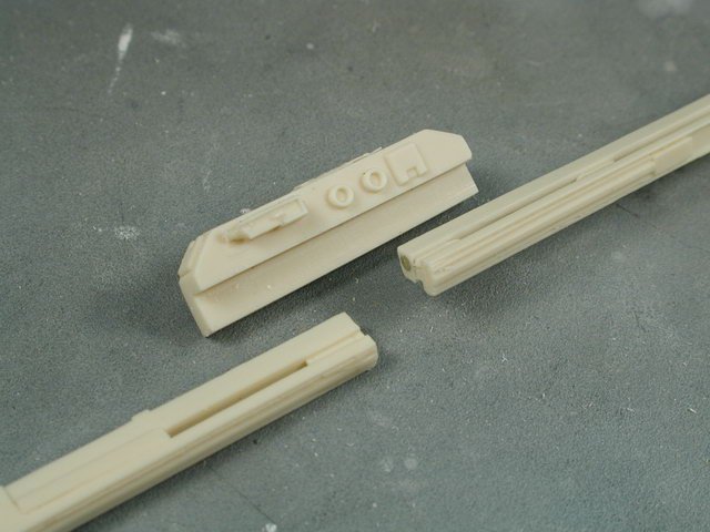
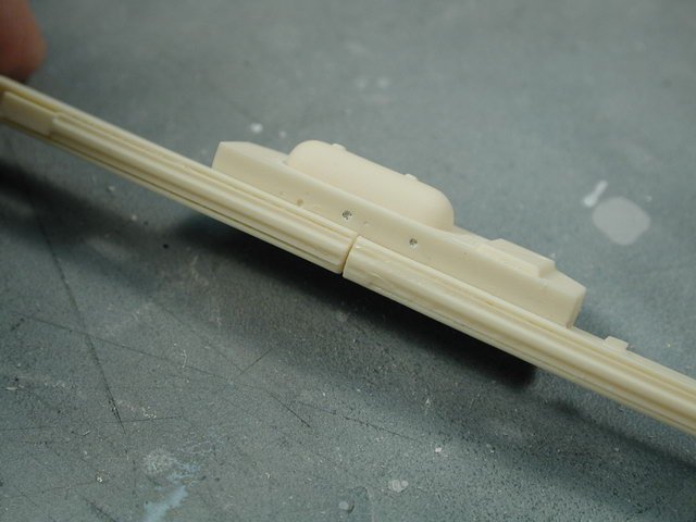
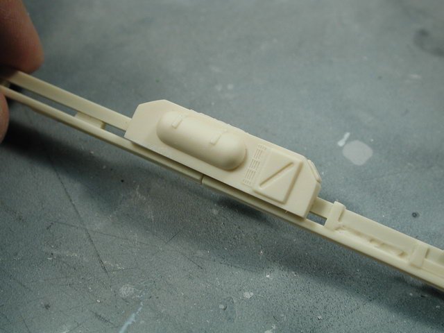
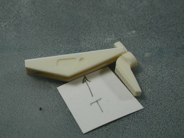
Thanks NB4M! I used to be a photographer (still a hobby) and my old Nikon 990 has a great macro feature (it allows me to focus down to a 1/2") and has a manual focus reticle in the view finder so that I am able to selectively choose where the camera focuses. Glad you're enjoying it - nice to know people are following along (makes the effort worth it). Although I was hoping that some of you who have this kit would build along so I could steal some of your ideas! On to the signal assembly itself! Again, there is the typical sanding and filing of the edges to clean the part up a bit. I shortened the legs on the side "fire" indicator so that it sat next to the main signal a little closer. I also filed the shape of the side markers a little bit to be closer to the line art. Now there are conflicting line arts (if you look at the reference drawings I posted earlier in the thread) - but I just picked an choose which shapes I like better. Again, there's a little excess resin on one of the triangular paddle like signals which is very easily remedied by a file and some sanding. Now if only someone can make white decals for these paddles that follow the line art! There's no way I can paint that small - but it would look great! Anasazi... are you there? I also started to add little extra bits of styrene plastic here and there to more match all the little sensor gak all over the signal. Here you can see a breakdown of the pieces showing the elbow piece that connects the signal arm to the signal assembly itself. Actually, I choose to invert the piece instead of using Gundamhead's instructions - because I wanted the larger end towards the arm, I believe it should go from big (base end) and taper to small (fragile) at the signal end. Additionally, if you look closely, I also drilled a 1/16" hole in the bottom of the elbow (the larger end accomodates this more easily) so that it can take the excess brass rod poking out the top of the arm. This provides a near friction fit and is a more secured attachment than just crazy gluing it to the top of the arm. I then started to detail up the signal itself - I wanted it to look more delicate like in the line drawings. On the elbow, I used a square file to file down the end of the arm so that it looks more like a pivot. I also drilled very fine holes with a pin-vise to mount antennas as per lineart. I happen to have very fine styrene rods which I used for the antennas, but I was considering fine wire or stretched sprue (a process where you melt the plastic sprue and stretch it to form fine antennas) but being the lazy sod I am, I just used what I had lying around.


-
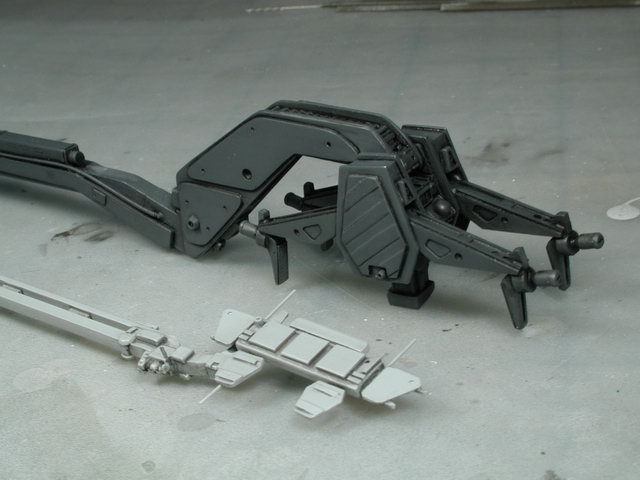
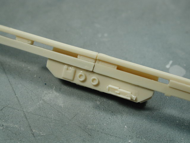
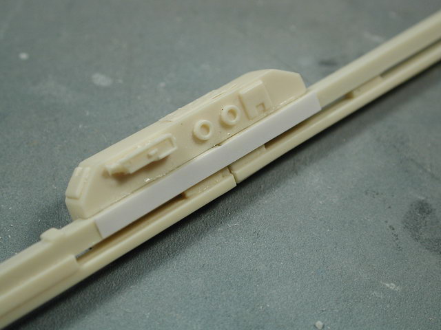
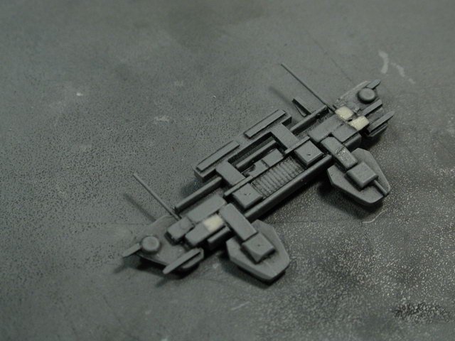
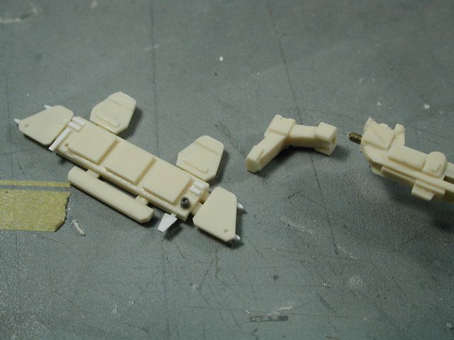
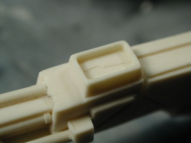
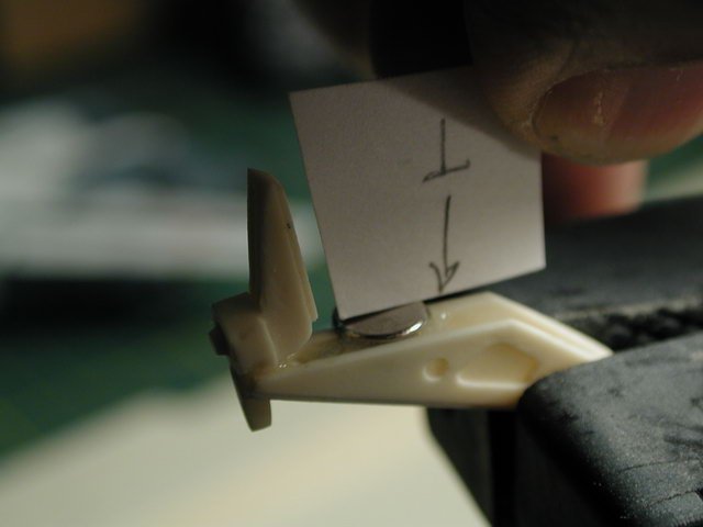
Now comes the joint portion. I filed flat the mating surfaces to make sure we get a tight fit and get rid of any extra resin that might be in there. I'm not exactly clear the exact orientation of the pieces - and its hard to discribe in words from the instructions. Do I lined up the brass rods and it made sense that the two bigger squared ends lined up. It doesn't really matter too much in the end which side the L-shaped joiner piece is on anyways - there are no real "canon" line art that says either way. After fiddling around for a bit, I chose the following orientation - I think it made more sense when you have the pieces in front of you than to try and decipher the instructions (word problems where never my strong suite ) Now I've noticed that after sanding, some of the surfaces had a few bubble holes which appeared. Instead of filling and sanding, I thought it was easier to just cover them up with a strip of styrene glued over top of the affected area.


-
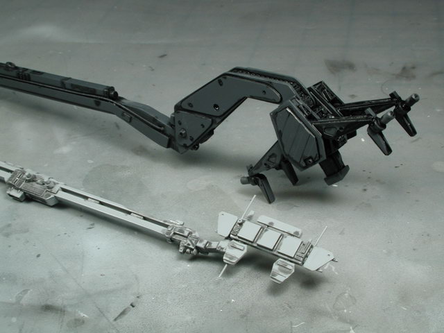
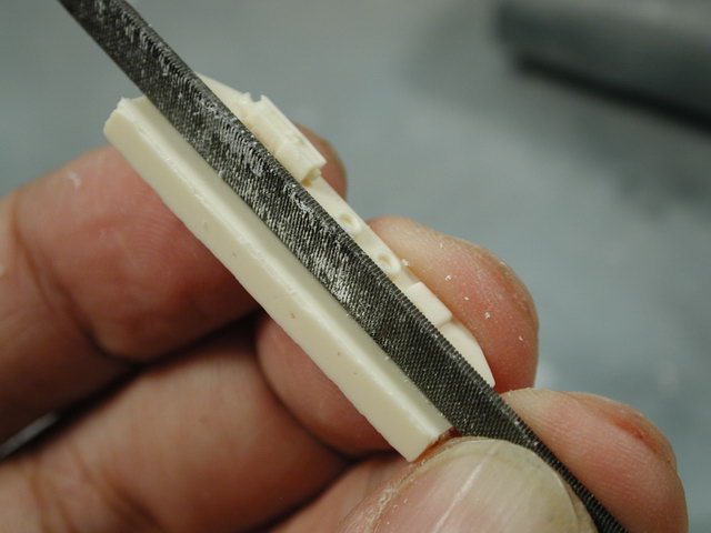
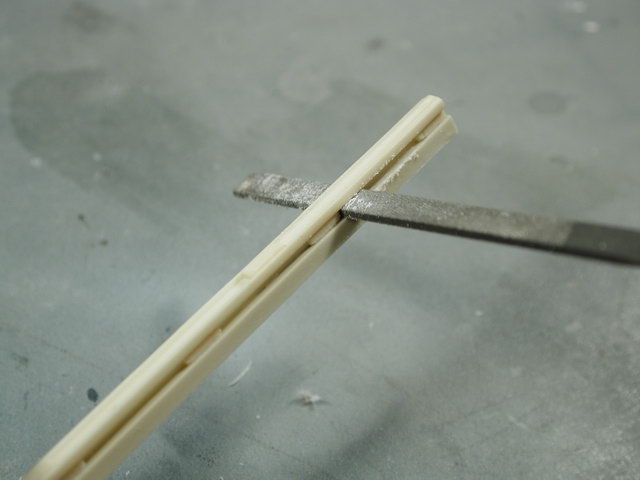
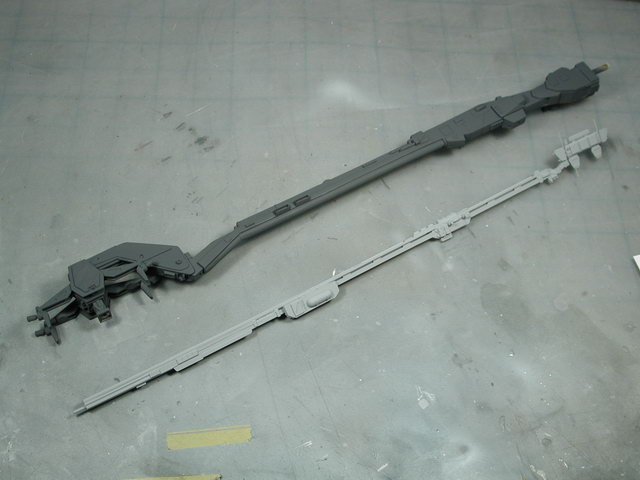
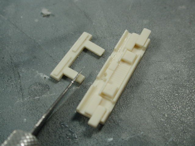
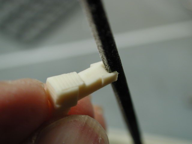
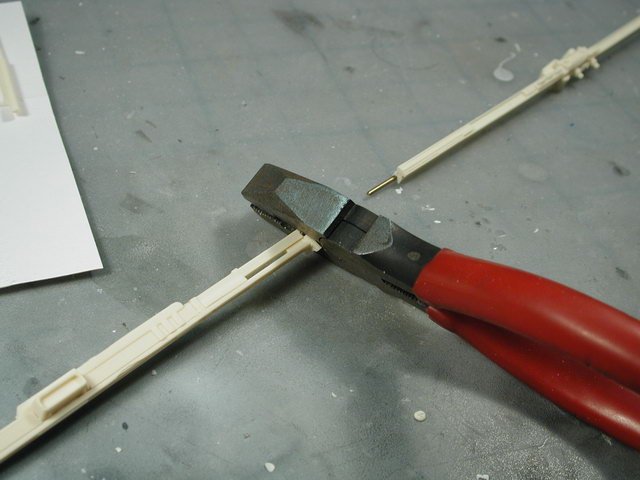
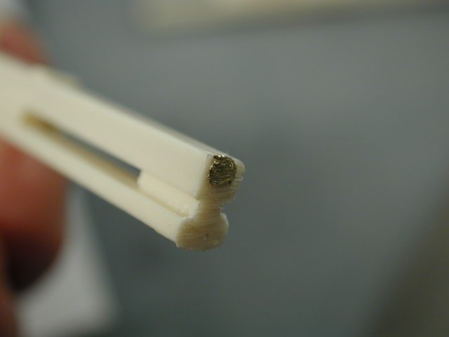
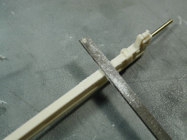
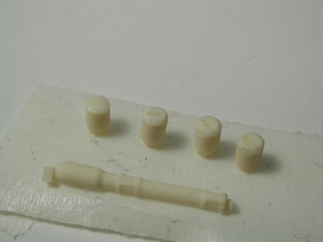
Thanks for the kudos all! I'm sure there'll be another round of casts. Personally, I'm hoping that they do a reduced version with just the upper part of the arm and claw/fingers assembly - I didn't realize how big this baby really is when its all together. Ok, I got a good chunk of time today! On to the signal arm. The first thing to do is trim off the excess brass rod that was embedded in the two parts of the signal arm. Look for the two ends that look alike, a larger square section with a smaller rectangular section with a space/slot detail running up the center. I would leave the excess brass rod at the base connector end and the signal connector end alone for now so that we have something to mount to. I just snipped the excess with a pair of pliers, and ground the extra down on a rough file the same way I did for the two parts of the main arm. Then I cleaned up the casting on the arm - there are some expected seams the run the length of the arm. A flat file was perfect to rough down the main areas (I don't mind sanding down extra - its filling in holes with putty and sanding that I hate! ) it also was the perfect thickness to get inbetween the slot and file the interior a little bit to get rid of some of the flash. On some of the other hard to get to areas, I used a x-acto knife and scraped it first. In the end, I sanded everything down with a 200 grit paper to get rid of any filing marks.


-
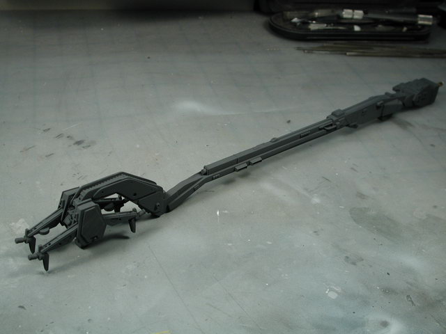
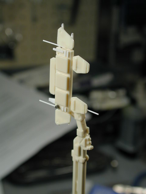
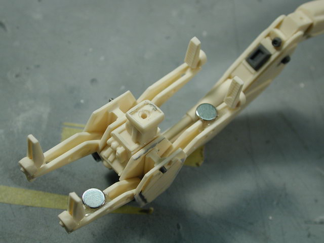
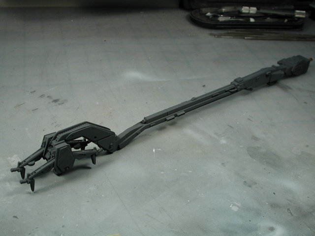
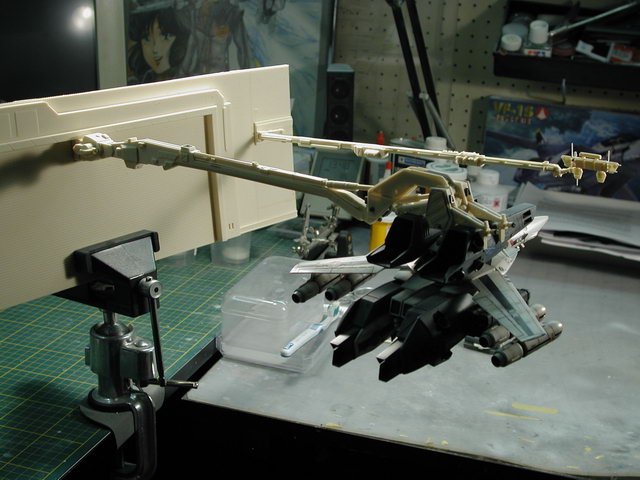
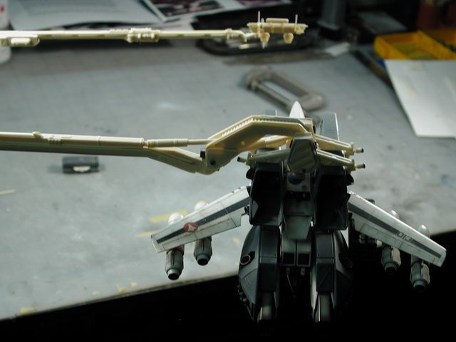
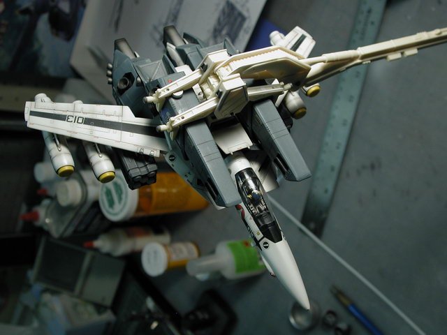
Okay, I didn't do too much today... I only pieced everything together - and it was the first time I had the arm and magnets holding the whole thing up. I am proud to say, that the two magnets did its job - it is very secure up there. I think the resin claw fingers or the wrist pivot joint or the three contact points between the Valkyrie and backpack will break before the magnets give up its hold on the Valkyrie. Hence I used 5min. epoxy on all these critical areas, and used a lot more than I needed - I gooped extra around the joints, but most of them are pretty hidden, so I do think it comprimises the overall looks too much. Wow! I never realized how long this arm was! It can be half as long and still work. Maybe it will allow some type of retraction mechanism like a ball bearing kitchen drawer hardware be used if there were a hanger to retract into?! (that's maybe another project some time in the far future) Maybe that will be Jesse or Gundamhead's next project - build a hanger for this - we could use just the claw portion to hang another Valk inside waiting in line? hint, hint... I don't know how I want it displayed now - originally I thought it would be neat to display it vertical, but its so cool hanging horizontal too! I can't wait to paint it! Thats when it will come alive. I think its time to assemble the signal tower next, tomorrow. I'm really happy with the way the arm has turned out. It would be so much easier if I was building a new Valk for it (most of the problems came in the retrofit portion) - I would place the internal magnets for the fastpacks farther back (but I couldn't in my case since I had place additional details in the rear opening of the fast packs that would of interfered with the placement of the magnets). Enjoy... till tomorrow...


-
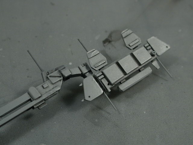
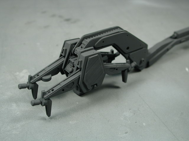
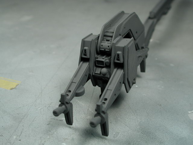
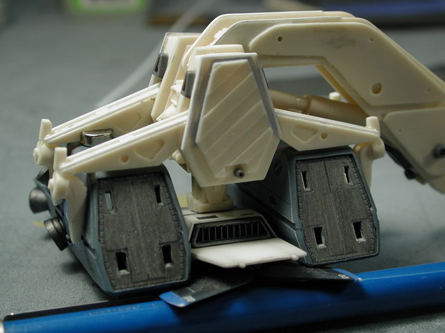
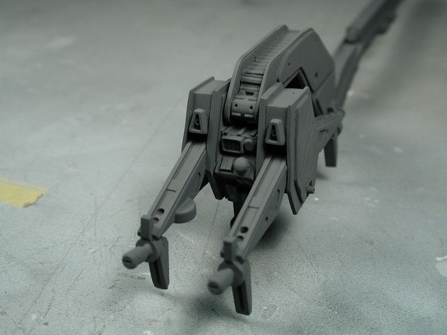
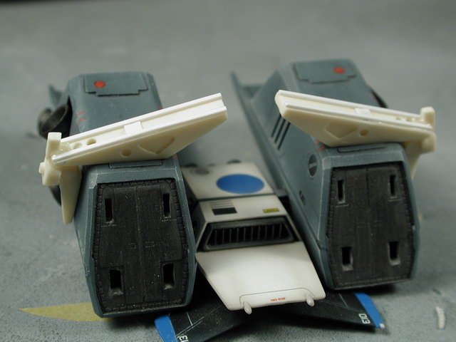
Here's a shot of the arm/claw/fingers assembly as I let the 5min epoxy to dry. I really gooped the expoxy underneath inside the finger plate area and fingers - since there isn't a whole lot of surface area for the glue to work against. I don't think it will be much of a problem, I'll paint it black let it dissappear into shadow and plus there's a supplied hydraulic actuator that will be fitted into place beneath each of the four fingers anyways. The pencil beneath provides the right orientation for the booster packs. The only thing is that when viewed directly from above, one of the rear arms is slightly askew (because of the placement of the magnets below the fast-packs, it actually pulls the arm incorrectly. However, its only noticeable directly from above - I may deal with it later if it becomes too much of an eyesore - but I just want to get all these parts properly glued in the right orientations first. Its a lot of pieces to get the angles right - work slow and carefully.


-
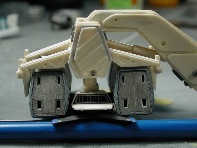
Here's a shot underneath the claw with the fingers friction fitted in place and the central umbilical shaft glued in place. I find that the entire assembly was a little askew - wasn't entirely symetrical along either axis. (Again this can be fixed by grounding off the resin pins to the central sensor piece between the two finger plates - but I personally don't feel that its worth the effor) This isn't a huge problem since its such a complicated shape that its difficult to decern this unless you are looking at it straight on or from the top. So I glued the umblilical shaft assymetrically towards one end to further hide the fact that its not perfectly symetrical. I find that if you purposely postion items assymetically, it can hide symetrical problems
-
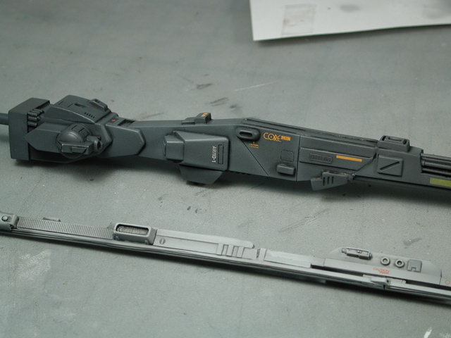
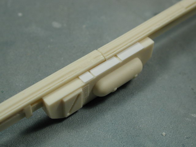
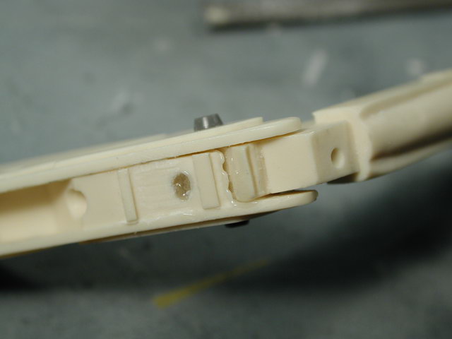
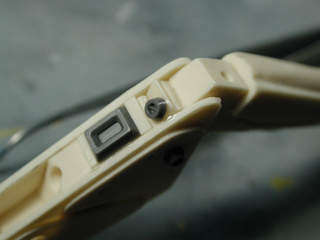
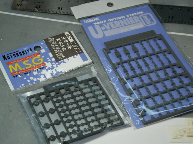
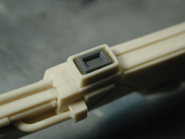
Remember I accidentally over-drilled and drilled a hole right through when I was mounting the wrist to the upper arm? Well, I found the perfect part to hide that mistake in the Wave Option parts (the same one with the minus molds). Here's a shot with the part glued in place and another cylindrical doodad to hide some excess epoxy glue that I was too lazy to file down. And remember that I'd said it was a bit of a pain or nusance to sand the seam in recessed areas - well I'll find something to fill it up instead of sanding it down. The same part works perfectly for this portion of the arm. So now I'm getting a little carried away with using some of the extra gak I have from this Wave Option kit - I like putting these vents over the top solid portion of the finger plates because I can hide the fact the the solid portions underneath don't line up properly against each other.

-
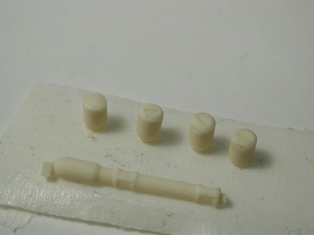
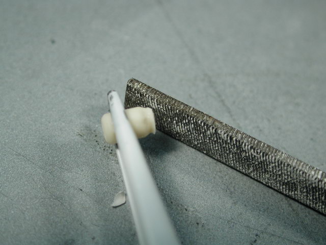
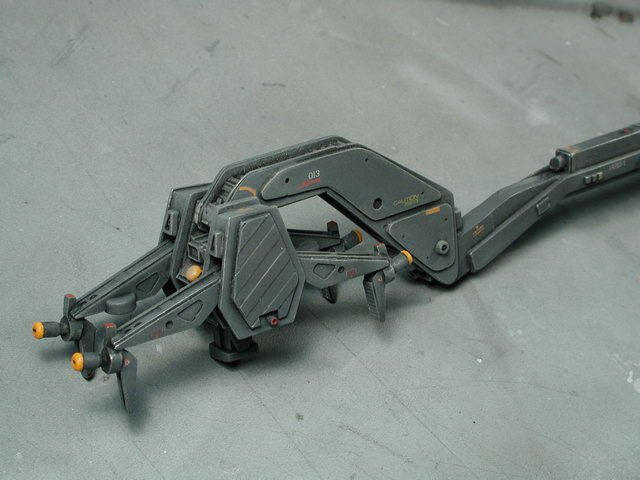
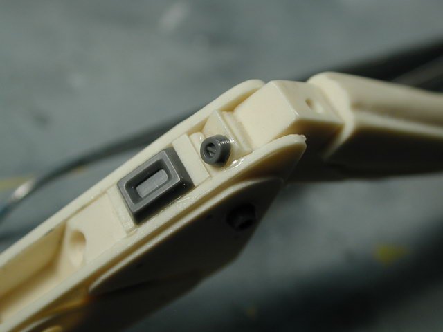
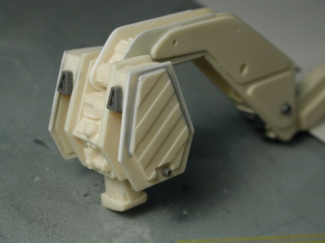
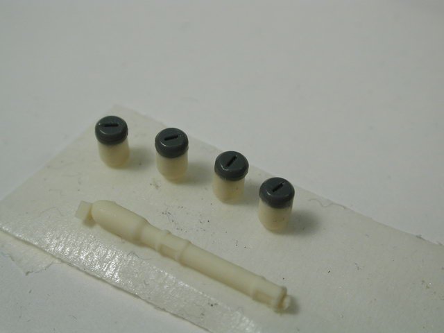
I would recommend using 5min epoxy to glue the little finger tips since the contact point is actually so small - I actually let a bit of epoxy spill out the top and bottom to ensure a proper strong bond. I then tacked the little lock cylinders that attach themselves to the ends of the finger tips. There's a cool minus mold detail on the ends of the cylinders, however, I was missing this detail on one of my cylinders and had a missing chunk from the other two cylinders (which would of been really easy to fill and sand). However, I happen to have some spare minus molds lying around from a few years ago when I ordered a bunch of option parts from HLJ. I think I've found the exact minus molds that Gundamhead used for his original masters So I thought I'd cut the tips off and mount my own minus molds in place. here's a little clean up to the cylinders themselves. Make sure you maintain the little bevel at the end when you sand them - I used a self closing forcept type tweezer and a file to clean up the bevelled end.

-
Yeah! I'll have to separate them very carefully in the future, I supposed I won't be doing it all the time (its just nice to have the option). Good idea about filing the magnets down... for me it might be just too much work to justify the effort. The rare earth magnets are like little pieces of metal and it would take a lot of work to file them to the correct shape - additionally I don't know how much weaker they might be due to the size decrease. Just trying to rough them up to be epoxied into the claw fingers were a lot of work. I wouldn't be able to "hand" file them down - I need powertools. So, today I started working on the claw finger tips. There's a bit of cleanup on the pieces themselves, just a little sanding here and there to get rid of any seam lines or un-eveness. I also cut a little cardboard guide to the right angle based on the fast packs that the finger tips should be glued to. Its really important to get these angles right - this will ruin the illusion that the finger tips are "gripping" the fast packs if the angles are not correct. Additionally, the magnets and the strong magnetic force interferes with getting a correct angle if I leave the fingers on the fast-packs. I wanted the magnets to self-centre - so I glued them inwards towards each other a little bit - because of this, I couldn't let the fingers sit on top of the fast packs, since they would naturally be drawn towards each other a bit thereby creating the wrong tip attachment angle. Also, I was afraid that any excess epoxy might drip from the tips onto the finished fast packs if I were to leave them on the fast packs to dry.

-
Hey Spatula, don't be so hard on yourself. I think it looks great! Especially considering its your first Valkyrie... its a tremendous effort. The most important thing is don't be discouraged - we are all learners here, and I for one, still have so much to learn!! If it makes you feel any better, I have yet (in my 10+ years of experience) to build a perfect model - or even one that didn't have some major mistake or flaw. Plus since we built it ourselves, we will always have a more critical eye and can pick out immediately where we went wrong or what the mistakes were. The key is getting it to the point were others can't pick out your mistakes - I've given up on trying to build the perfect model long ago! Criticisms eh... (I'll reply to your PM here instead - since I think others will benefit from the comments too) well, first off - did you hand brush or airbrush the white coat. It makes a lot of difference (I can't really hand brush a smooth coat to save my life! and really rely on the airbrush to get a clean even coat). As mentioned before, I'd concentrate on getting rid of the seams - in the beginning, I'd use more putty (which results in more sanding) but its safer to use more putty and sand to get rid of the seams. It also looks like you did your wash on a flat finish paint - I see that the wash seem to have stained areas around the panel lines. The oil panel wash works well on glossy or semi-gloss surfaces - so you can wipe away the excess wash without staining the surrounding paint. Lastly, does your digital camera have a white balance setting? If it does, set it to tungsten setting, it will neutralize the orange cast in your photos to give you a better colour rendition in indoor lighting. Don't worry about stealing anything - I post here to share, and I think its a great compliment when I see others use my suggestions. Actually, I "stole" it from Tenjin the artist anyways