-
Posts
2630 -
Joined
-
Last visited
Content Type
Profiles
Forums
Events
Gallery
Everything posted by arbit
-
Are you sure that is printed not resin cast? I dont see those print lines. Nice little SDF-1 there. In many ways I like the look of those old molds better than the modern kits. Any more pics?
-
I listen to takering. Thanks dude! I was really hating this figure.
- 1588 replies
-
Yes stay right here! Its interesting for newbies like me to follow your learning process with 3D printing.
-
derex, Looks like the seam line drill sergeants got to you before I did. Get those legs smooth and shiny!!!
-
Looks fantastic Thom! Could be an 80s movie prop.
-
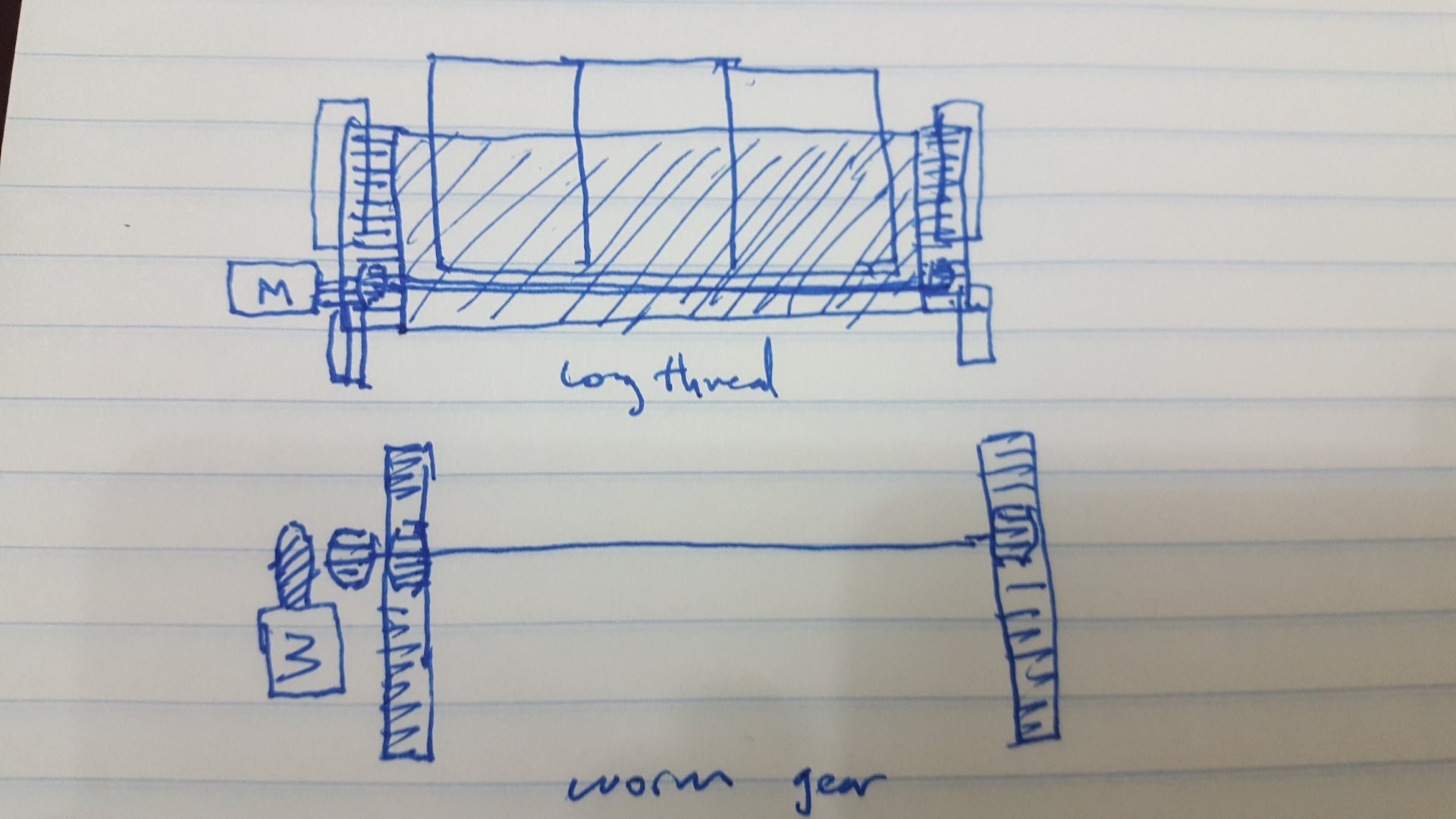
Thanks. I have a lot to learn about gears to figure this out. I'm thinking about a double rack and pinion. There are two options, a long thread vs. a perpendicular worm gear. From what I know the worm gear will wear down gears from the friction and may slow down the speed. The long thread may be hard to stabilize. I wonder if anyone knows which option is preferable and why?
- 137 replies
-
Yes, I've wracked my brain trying other ideas. Draw me up what your thinking: the belt drive and the "mechanical linkages".
- 137 replies
-
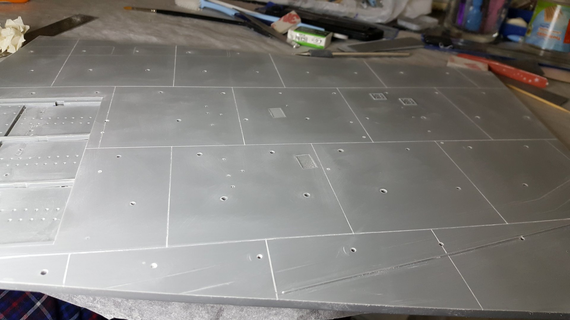
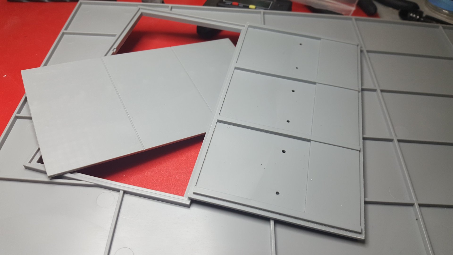
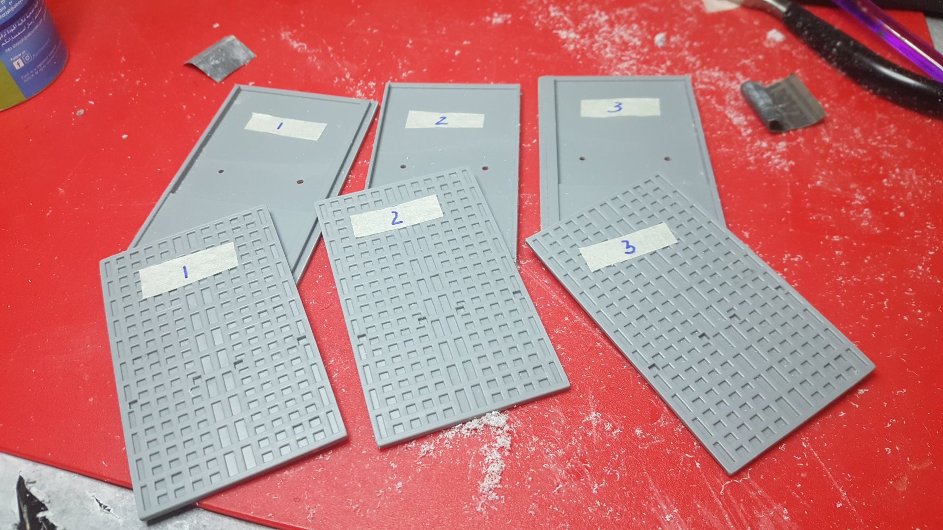
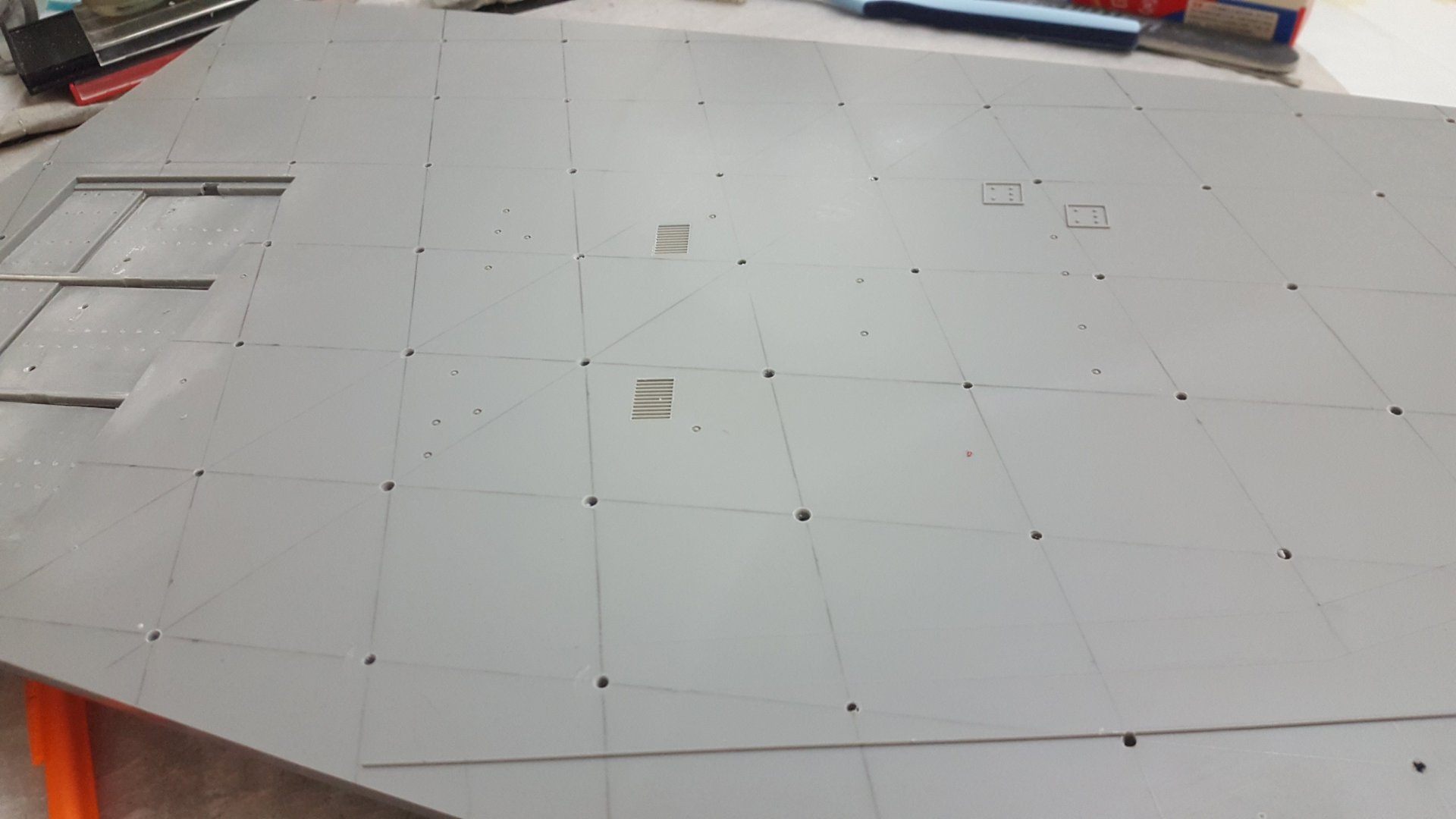
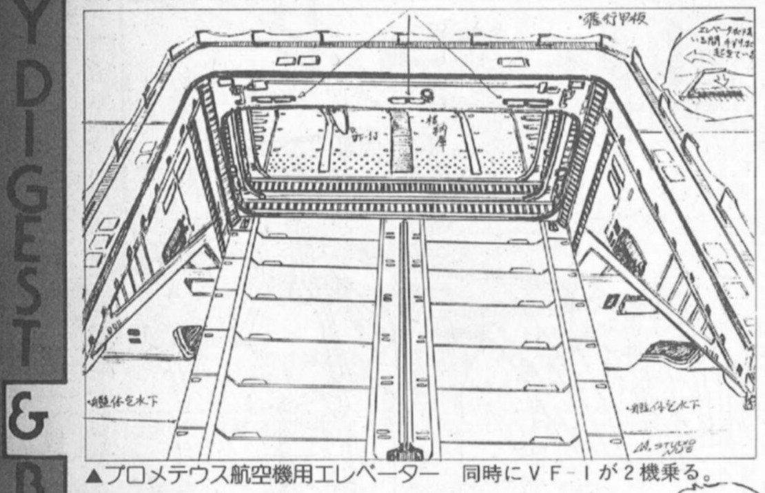
There are 1/72 Blast Deflectors on Shapeways with workable actuators, but they are too large to fit my Trumpeter deck and other kits I am aware of. So you have to build your own flight deck, which is probably a good idea, because all you need is a 5mm thick pla plate and add the details, which I had to do anyway.
- 137 replies
-
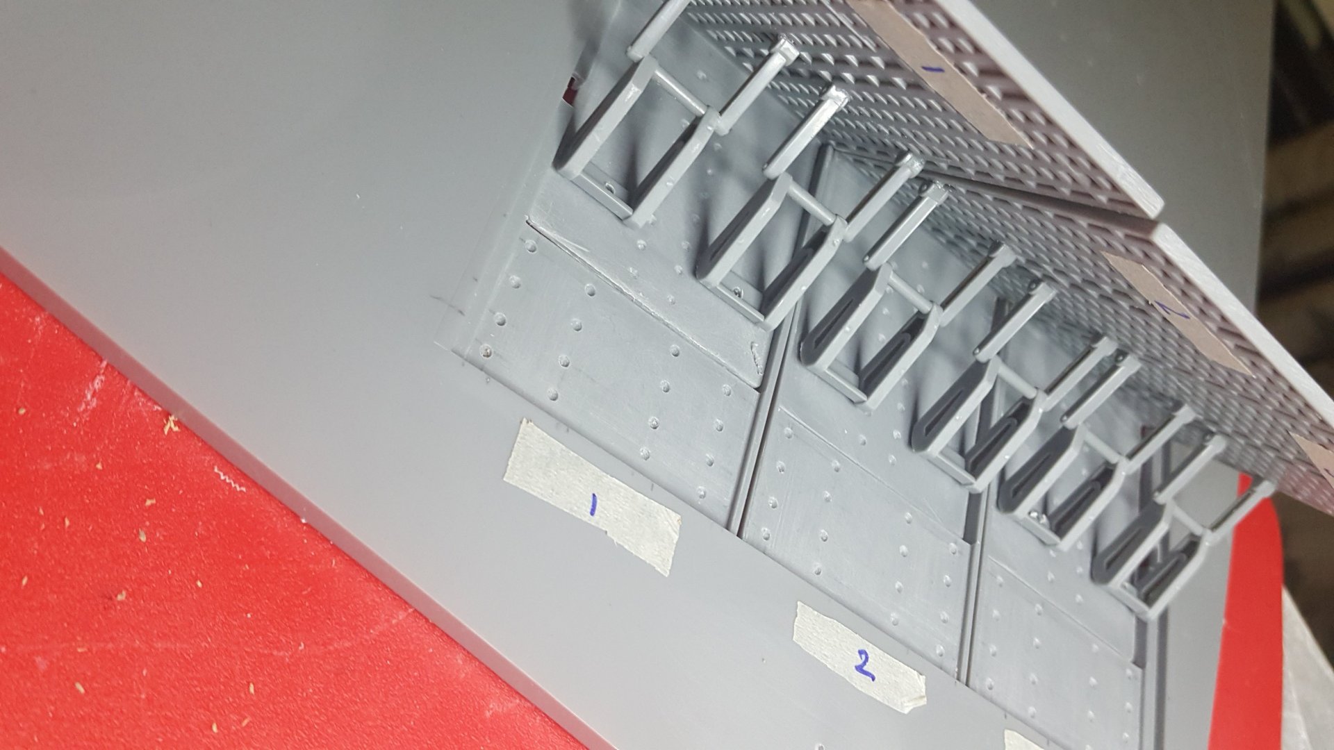
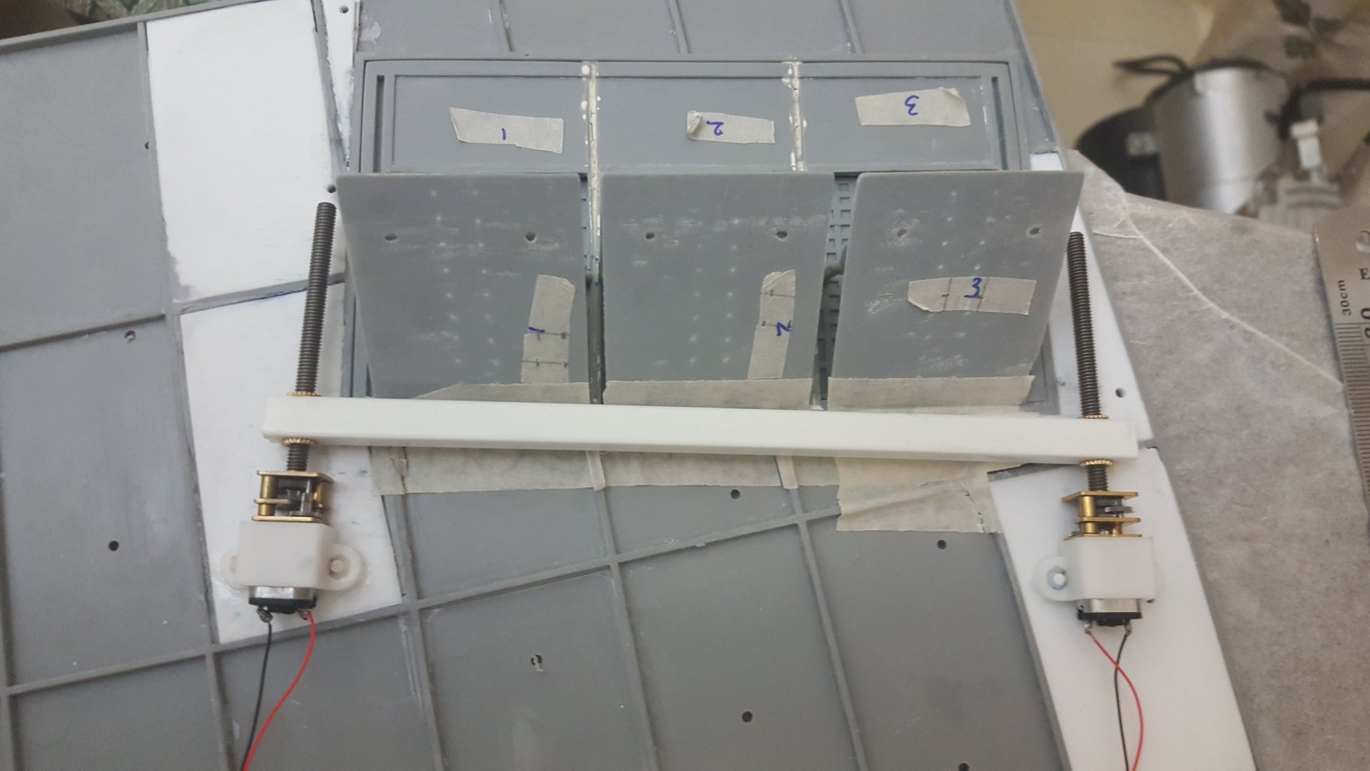
This is a test of my mechanism to raise the Blast Deflectors. It has some issues, so I need to make it more reliable or come up with a different approach. The way it works is the styrene bar raises the three deflector panels by pushing them up, and then the deflectors drop by gravity. I may actually end up using paper hinges, because I need zero resistance for the deflectors to drop back down. The angle of the bar causes them to rise in sequence. The problem with the twin motors is they get out of synch. The possible solution I found is that if the limit switches are on only one motor, with each up/down cycle they can realign, because the bar hits the motor on one side and is forced to a stop, while the other motor catches up and hits the limit switch. (I need to add a second force stop at the top of one thread.) But I have a couple problems with this solution: 1) The motor on the right sometimes locks when the bar hits it and forces the motor to stop (I ordered small springs to see if that prevents the locking). Even if I switch motors, the locking still occurs on the right side, so it might be an unlevel platform or a slightly off angle (The threads have to be perfectly parallel). 2) I don't know if this forced stop for a couple seconds while the other motor catches up will burn out the engine. I am using a boring 1/72 Trumpeter FLight Deck, but trying to add some details to spruce it up, and photo etch tie-downs.
- 137 replies
-
Not sure which TV/movie version that is. I am strictly TOS, and your wessel has the classic lines I like. Nice start Pengbuzz. Hope you mix in details from different line art and screen grabs, in addition to the kit.
-
Kylwell, That's a nice little shop. I wonder if their turrets are fully drilled out tubes for lighting. Mechtech, the scratch work looks gorgeous. I almost don't want you to prime it, because I like the different materials! ...I need to get a mill! Derex, How is the Q-Rau going? The thing must have nightmarish gaps to fill. Warm up your files and putty
-
Thanks for the nice comments. I'm putting her on a temporary base, while I work on the flight deck and lift.
- 137 replies
-
- 1
-

-
Thanks Thom. You dont know it, but your comments influenced me to think up a cooler cockpit. The problem decals were only the Diamondbacks. The Hasegawa decals were just fine.
- 137 replies
-
- 1
-

-
I've put up a new WIP thread in the Model Kits section for the bluetooth valk if anyone is interested.
-
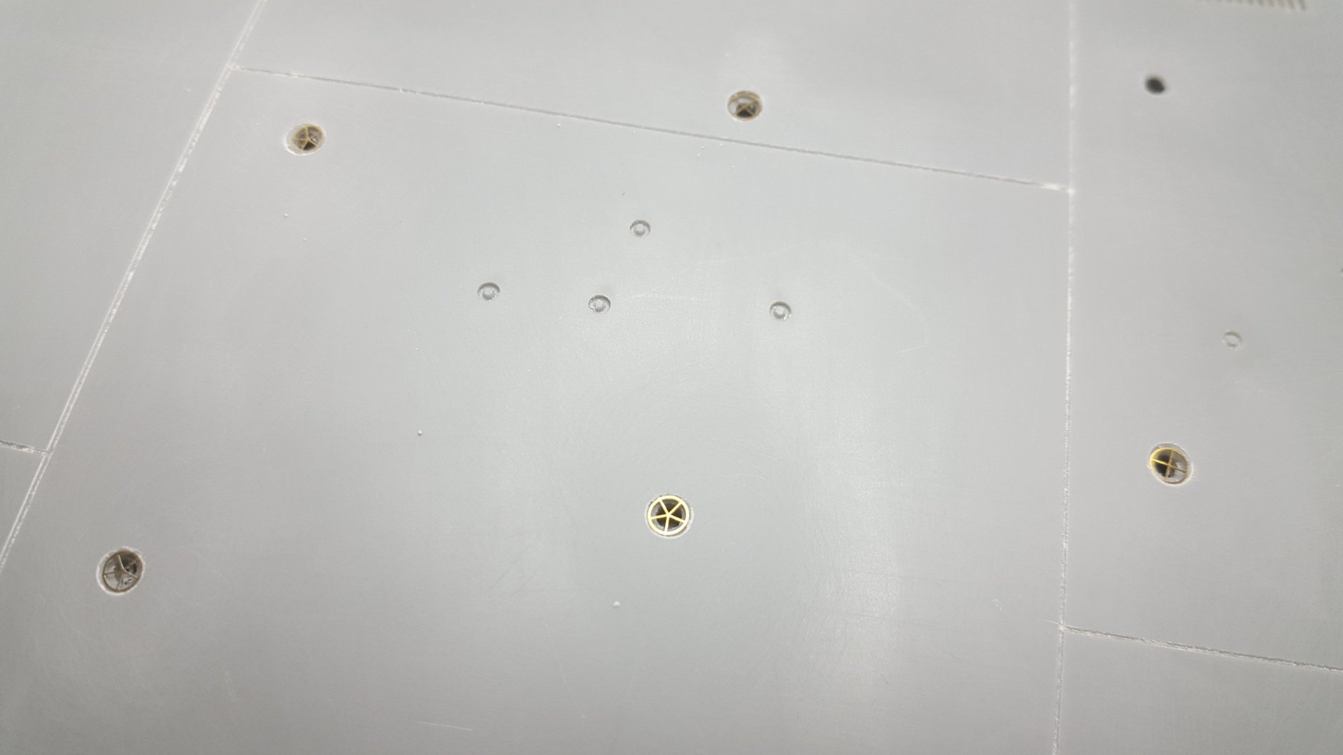
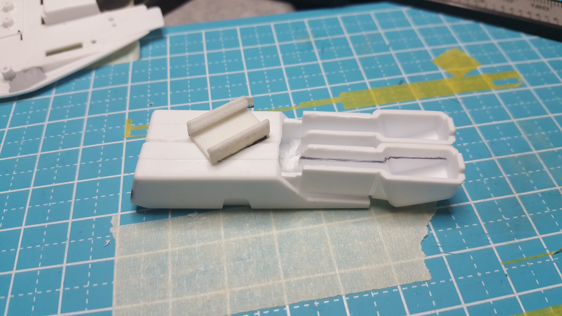
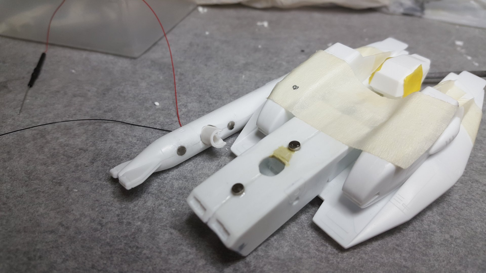
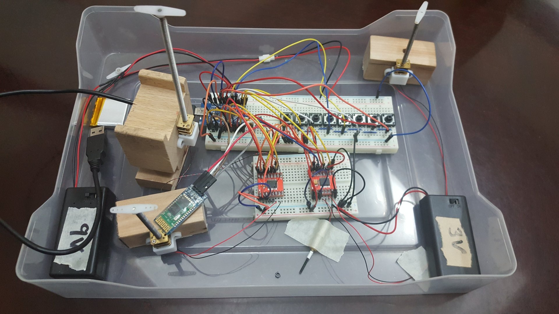
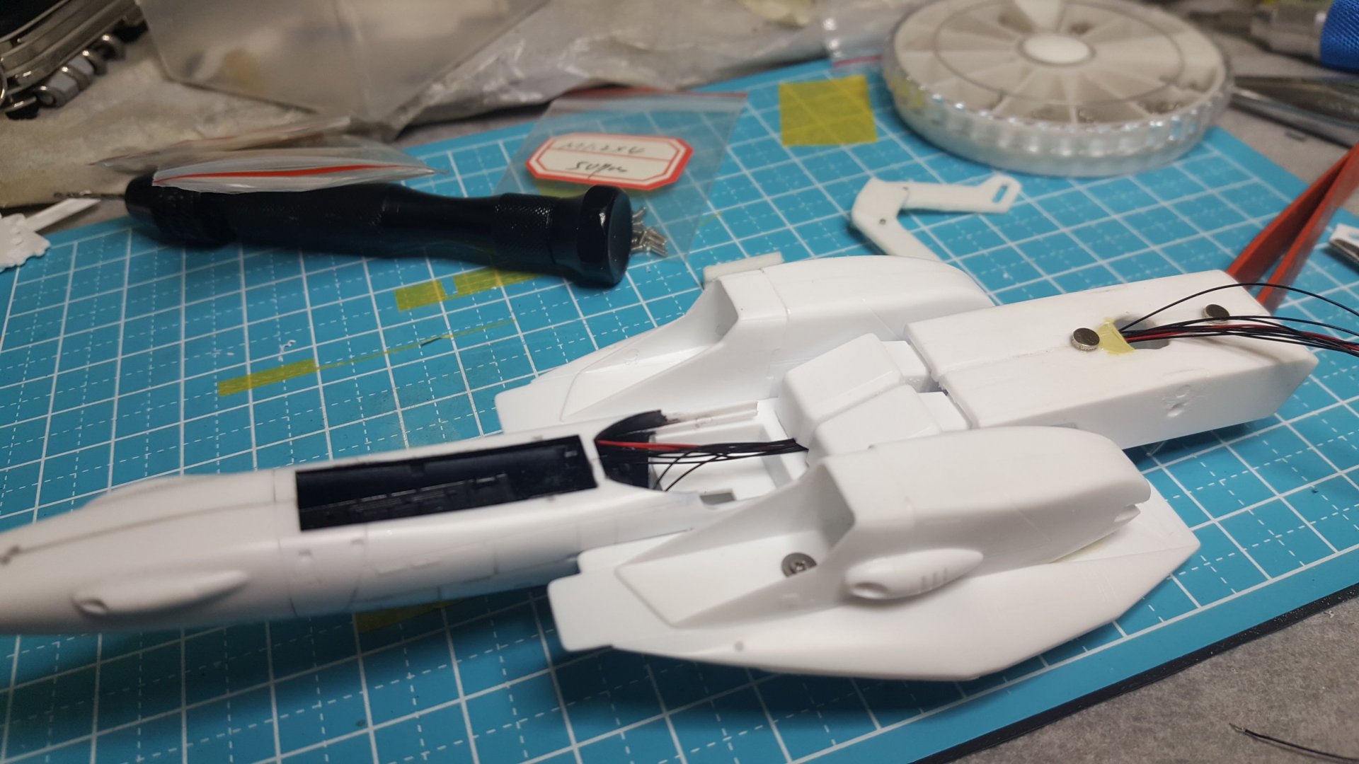
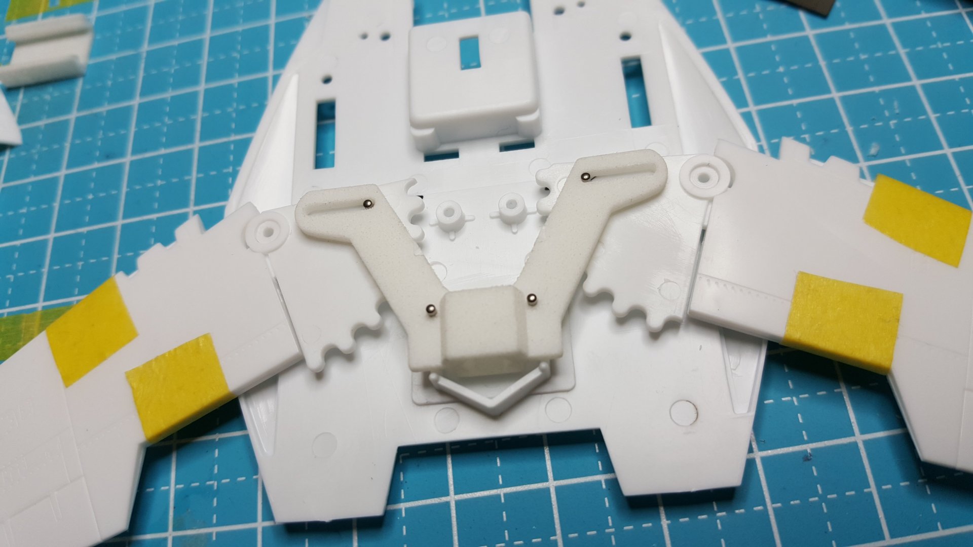
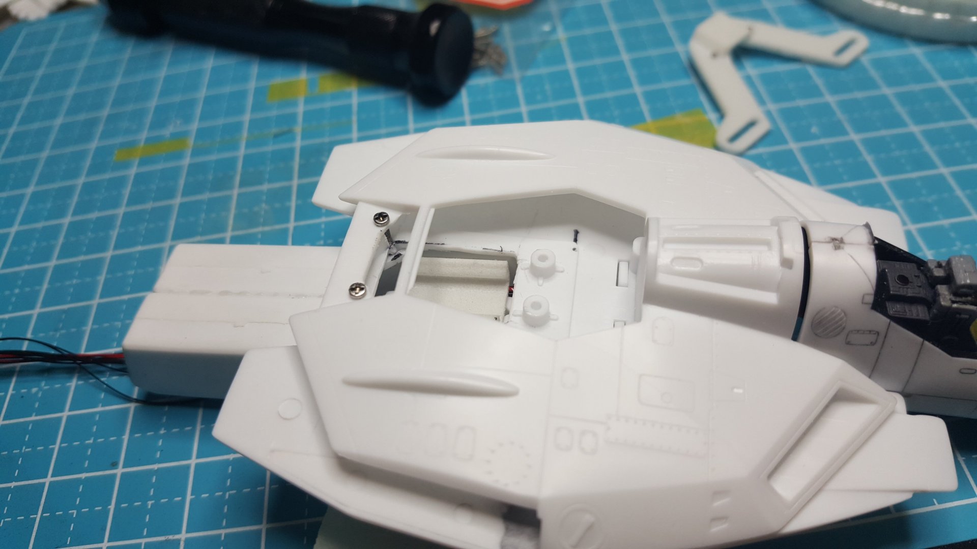
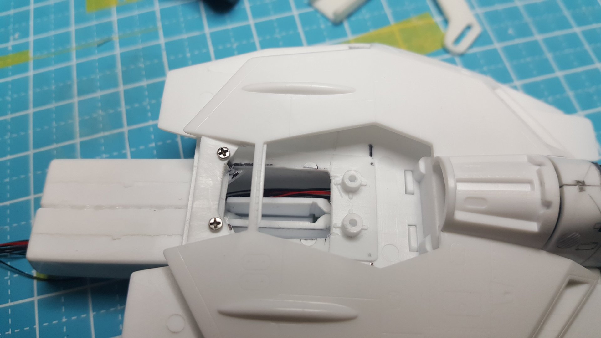
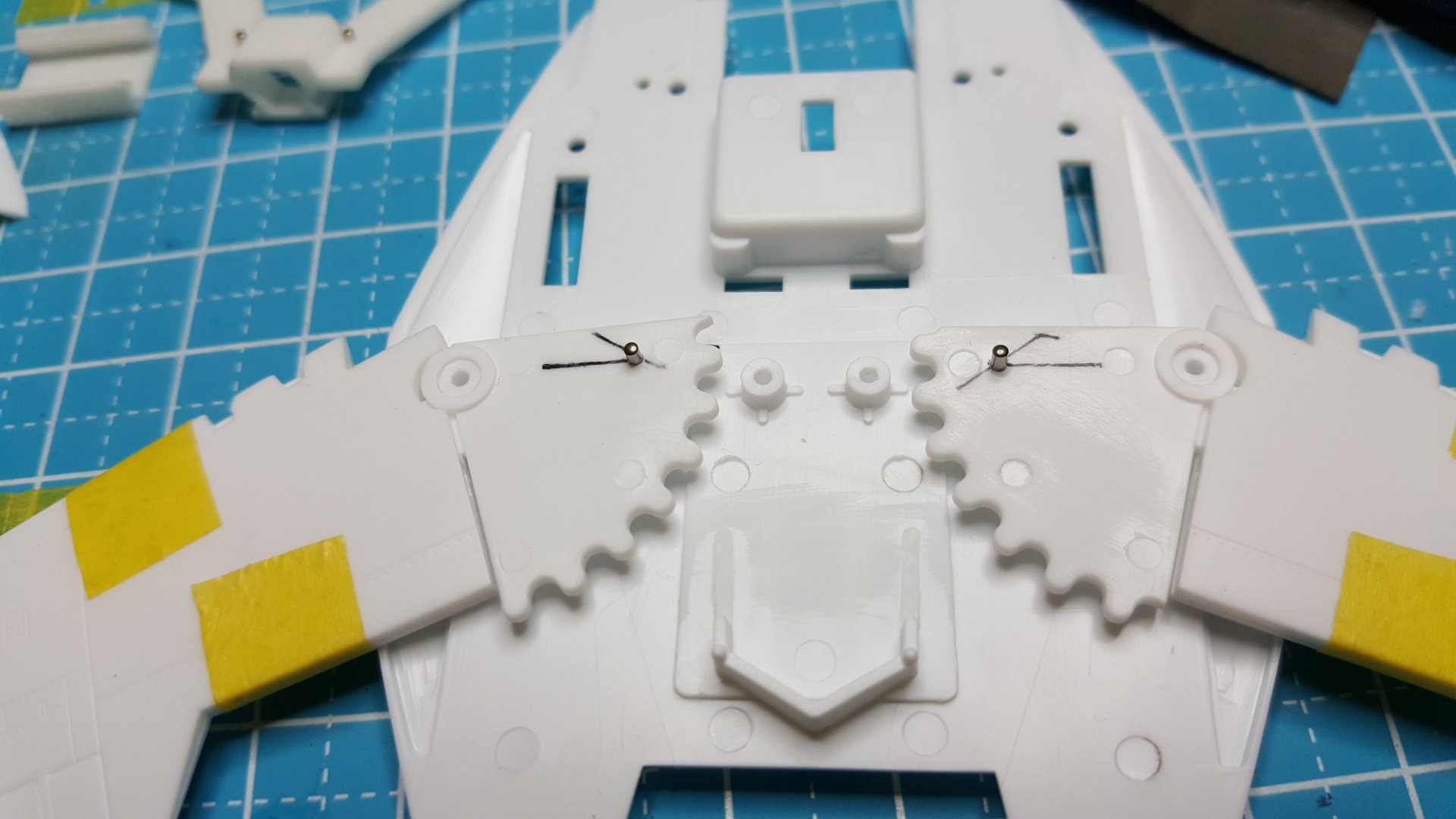
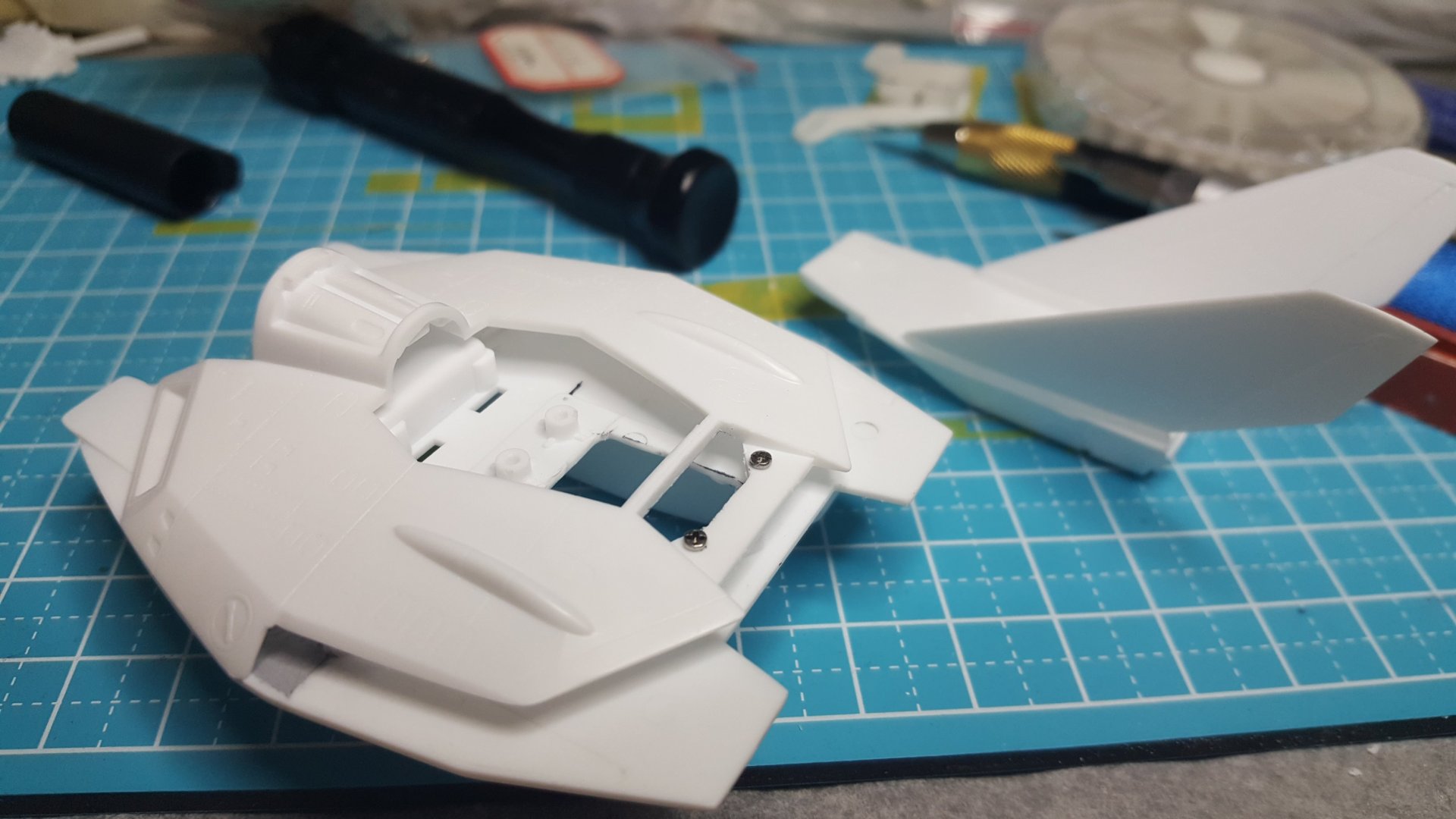
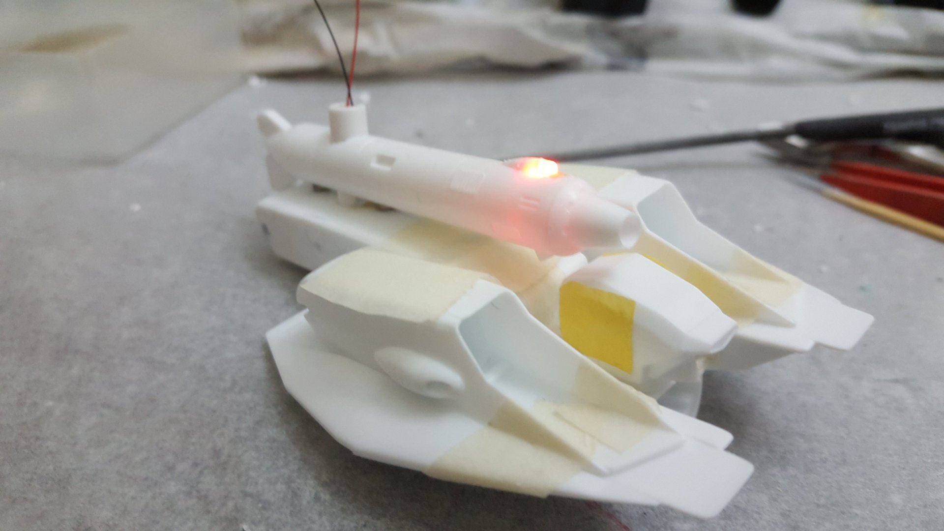
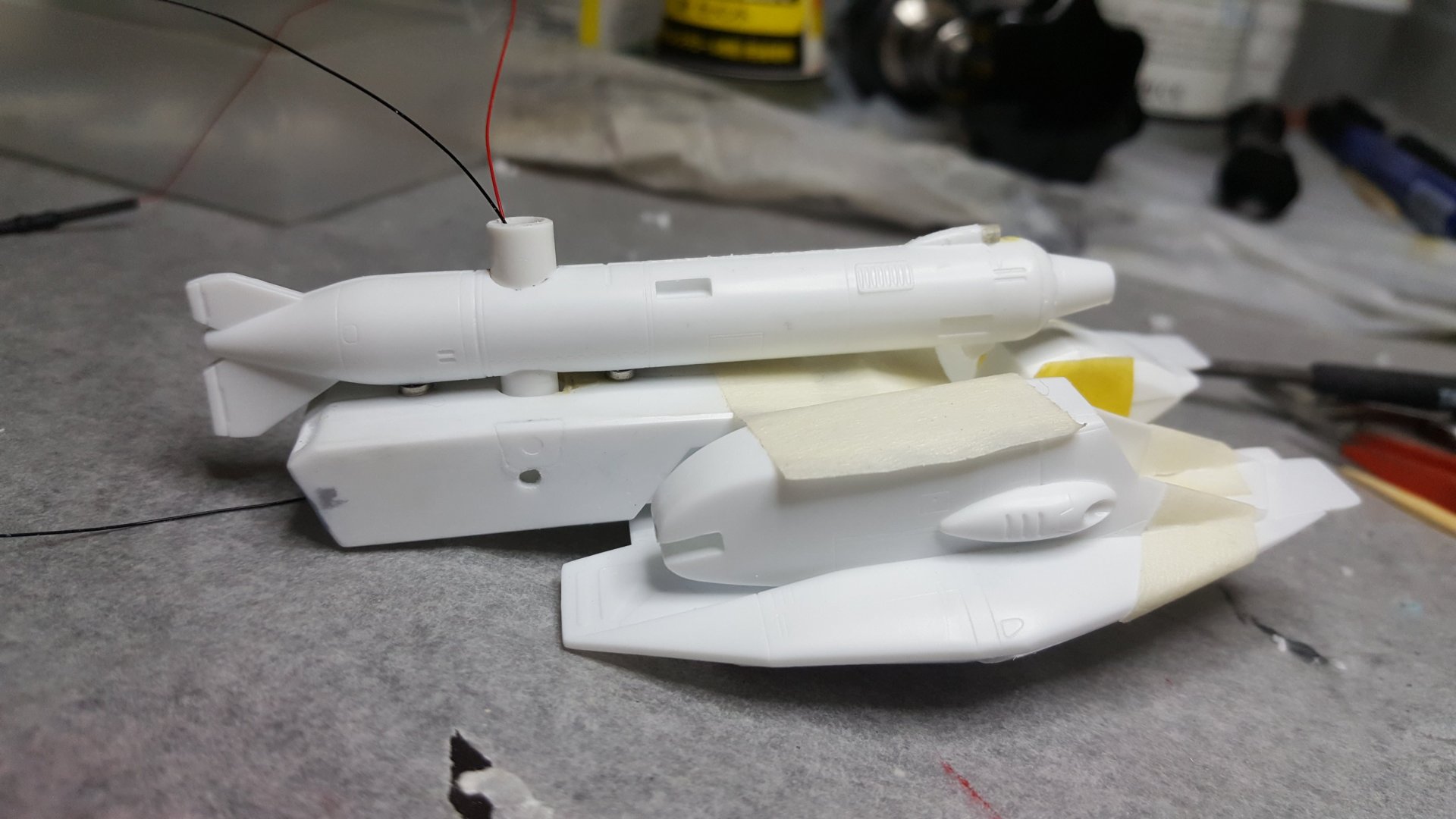
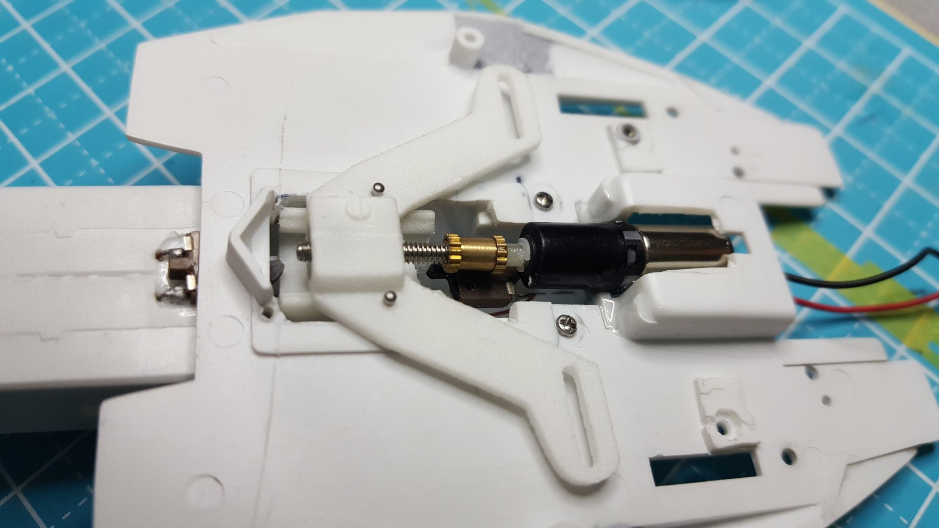
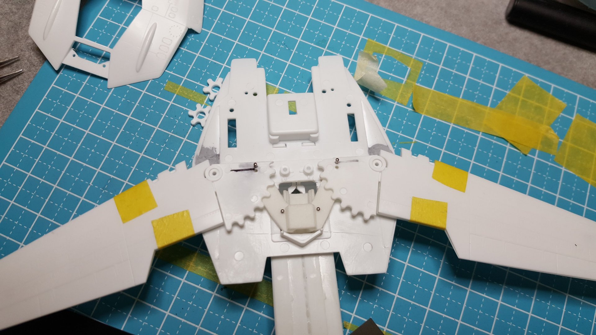
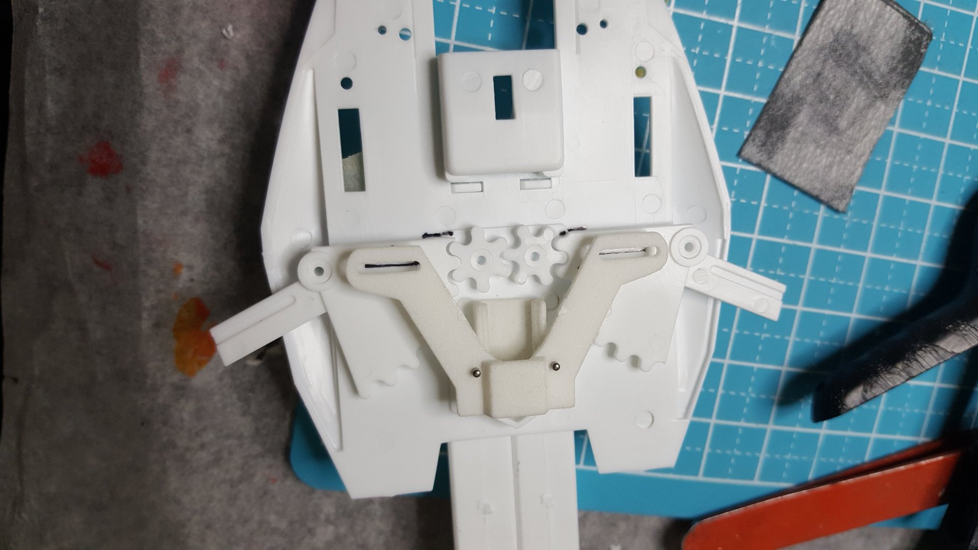
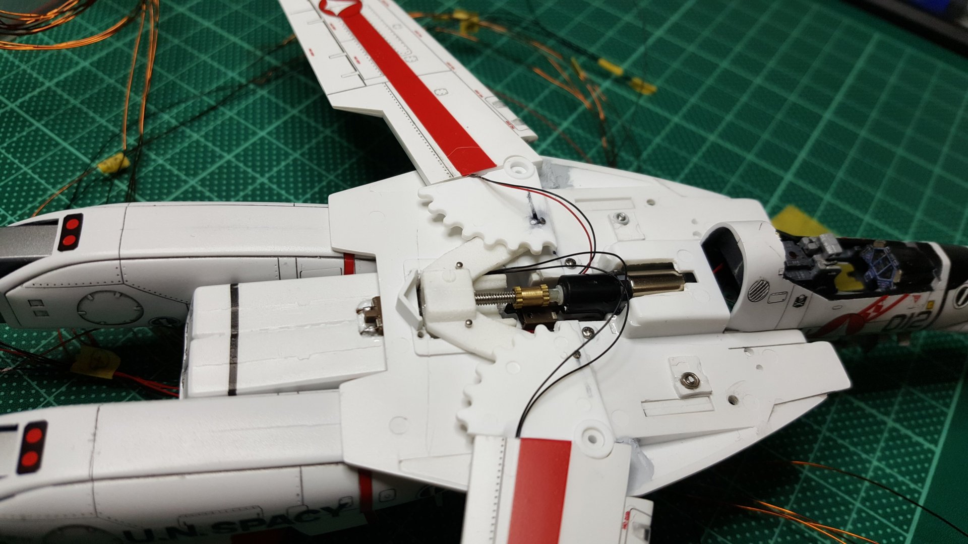
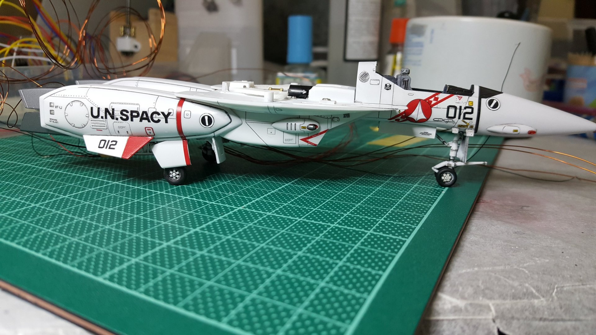
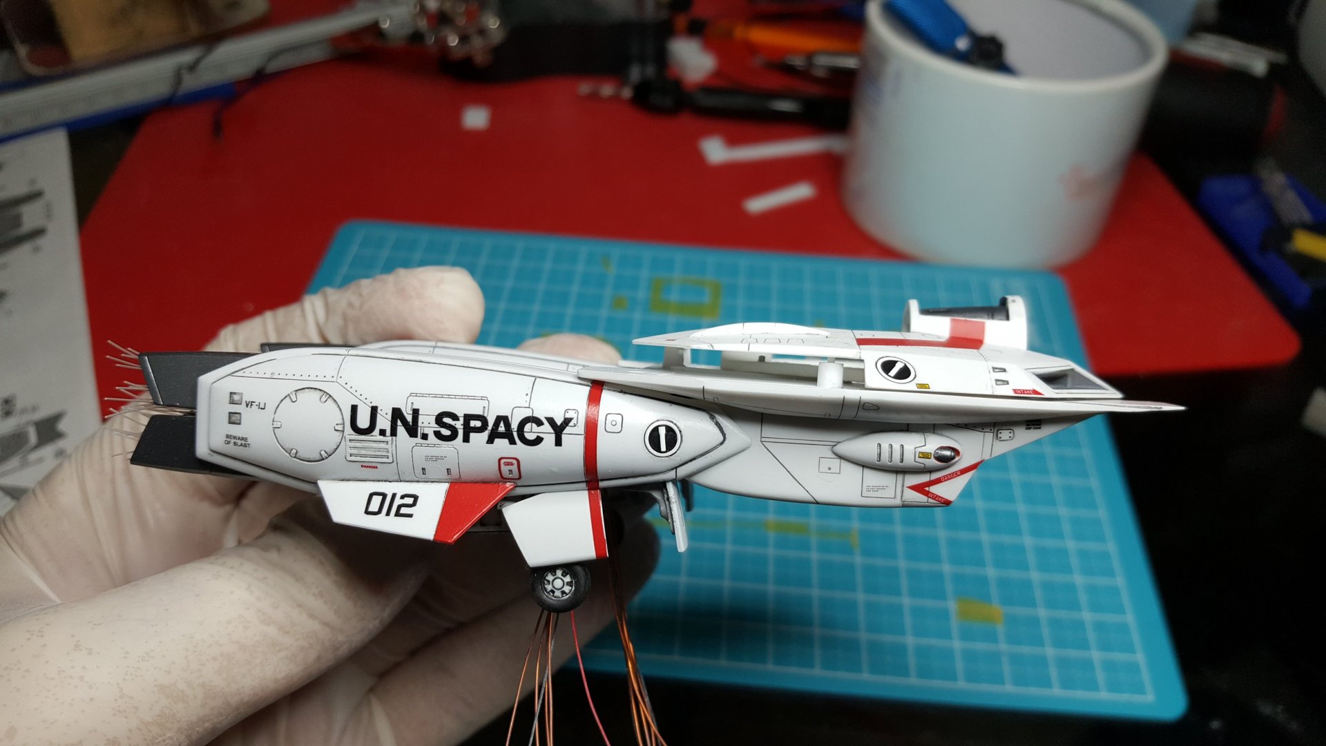
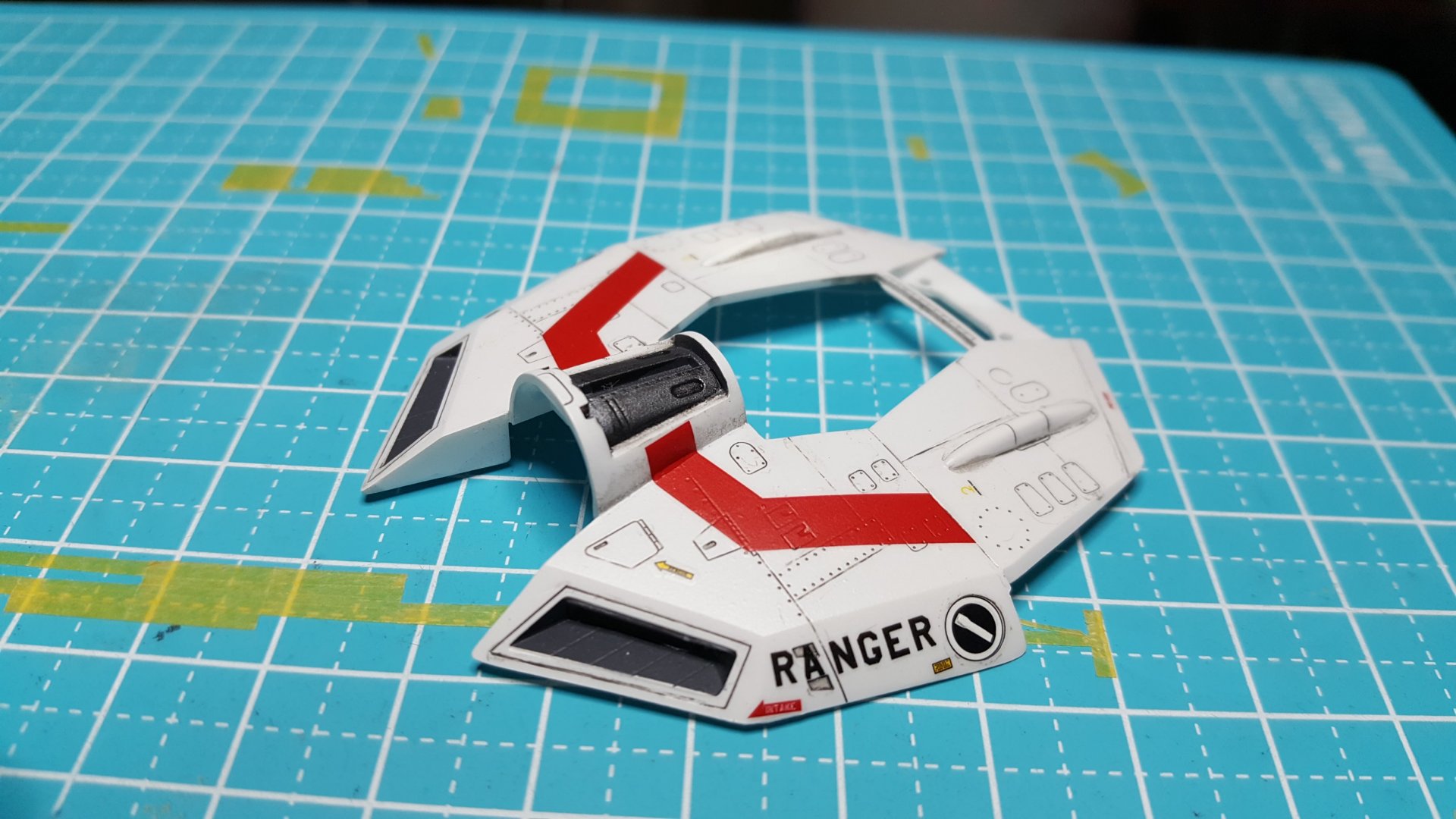
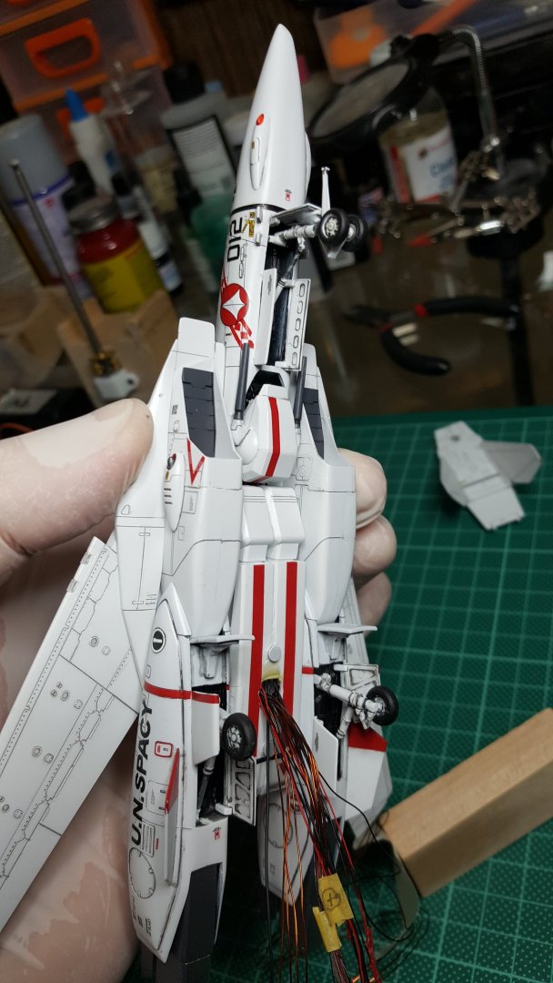
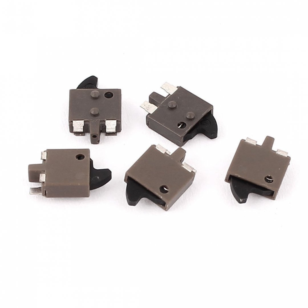
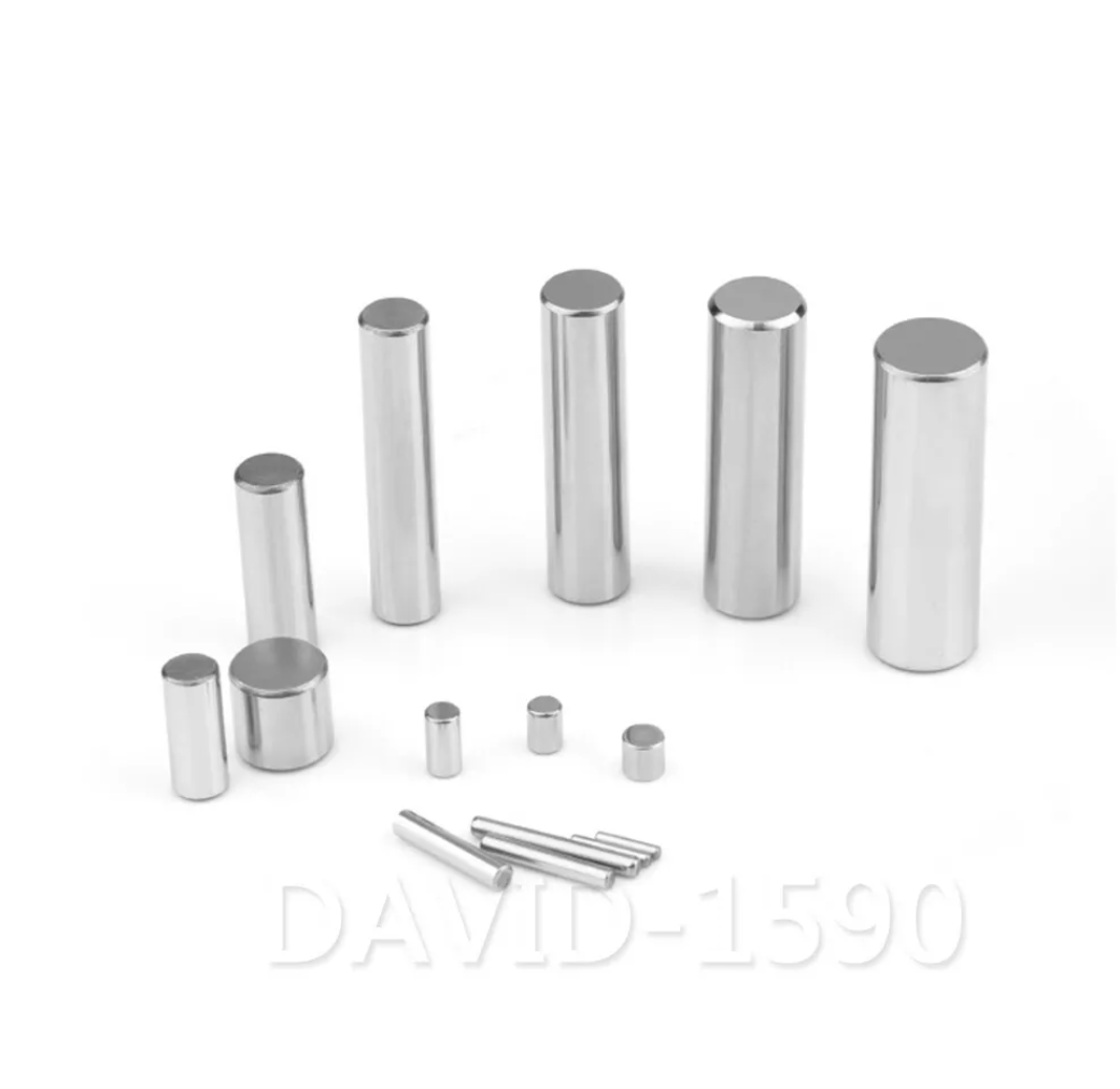
This is the step-by-step WIP for installing Xigrid's Gear: First, I use the existing gears to mark the full open and full close positions on the wing arms. At the intersecting lines, I drill 0.9mm pin holes for placing the 1mm Dowel Pins, which will connect the Gear to the wing arms. Second, I cut a rectangular hole to fit the Gear Track. This hole will be elongated later for the motor as well. Then I mark out a line on the arms measured to fit the Gear Track. I sand this down until the Gear sits flush on the fuselage. The arms are the most important part for motorizing the Gear. They hold the Gear Track and the motor. All the wires for the leds also run under the Track, and out from under the valk. There are no wires impeding the Gear itself. Below you can see all the wires running under the track. And the Track is epoxied above the wires for the Gear to run without any wires in the way. Then all the wires run out the bottom. I have prepared magnets to connect the gun pod and a small tube to take the wires into the base. Below you can see the placement of the two limit switches, the motor, thread, and knurl nut. These tiny limit switches are Normally Open, therefore you need to use coding that tells the motor to stop when a limit switch is hot. The wing led wires also run under the track with some give to allow for movement. All the wires come cleanly out the bottom. There are no other electronics in the valk. All the resistors and control boards sit outside the valk and will be hidden in the base. The components running the 4 motors are an Arduino Micro, HB-06 Bluetooth Driver, and 2x TB6612FNG DC Dual Motor Driver. The entire project prototype below will be hidden in the base.
- 137 replies
-
- 1
-

-
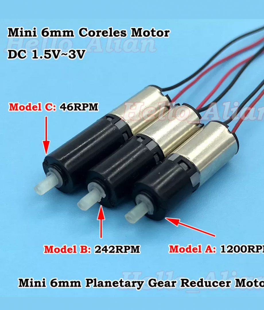
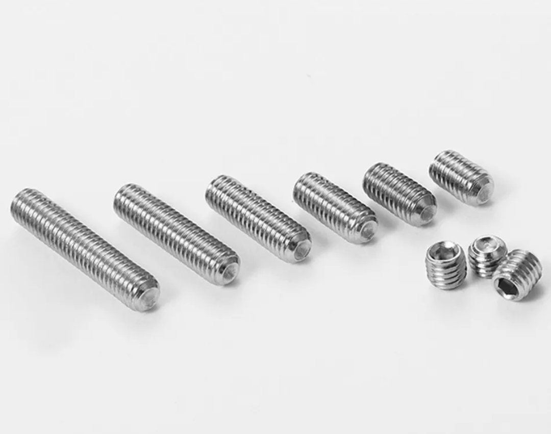
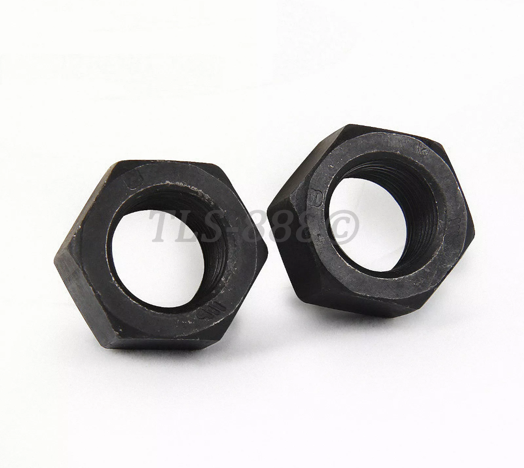
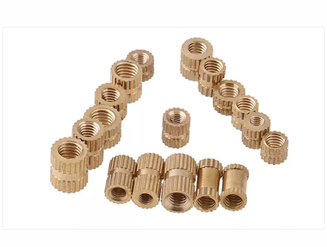
Installing the gear to motorize the valk requires the following parts: - Xigfrids Shapeways 3D printed gear - 1x M2 nut - 1x M2 * 6mm knurled nut - 1x M2 * 16mm cup point socket screw - 1x 6mm planetary gear motor 3v 242RPM - 2x Micro dvd Limit Switches N/O (9x5.5x2mm) - 2x 1mm x 5mm Dowel Pins
- 137 replies
-
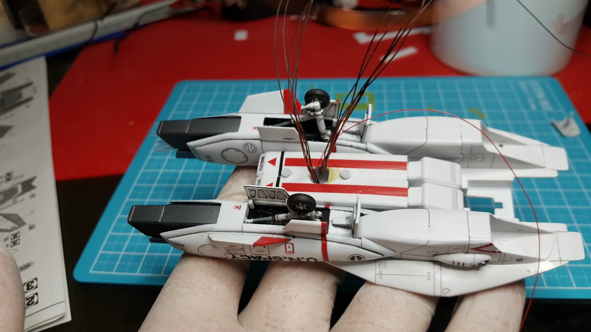
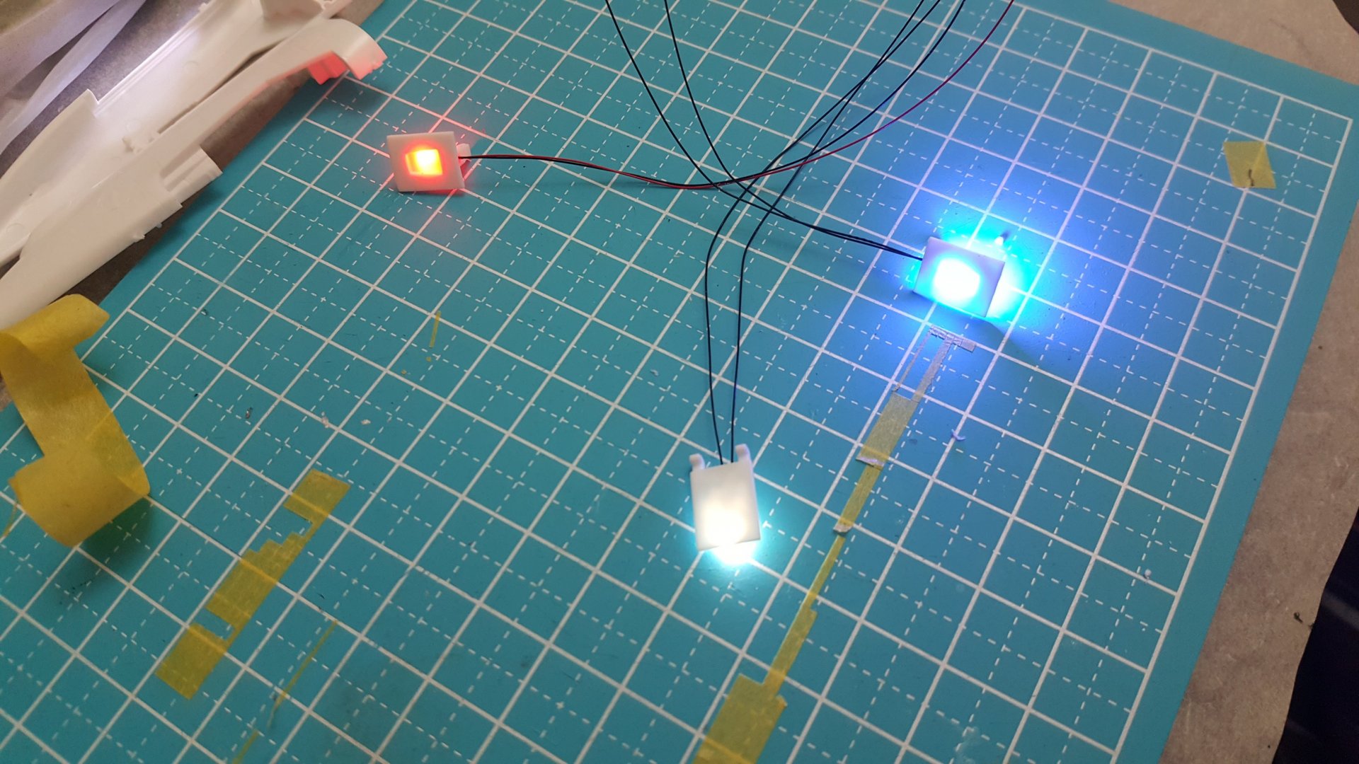
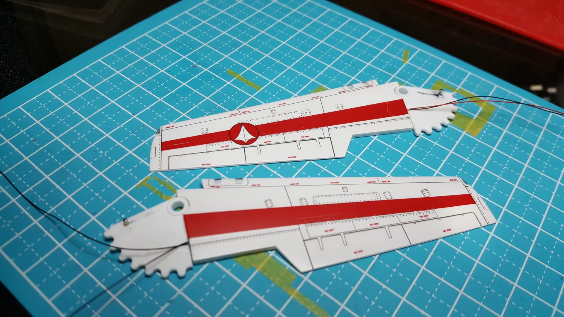
The landing gear and wing leds are 0402 smds which I get pre-wired on ebay. I drill a hole to pass the wires through the gears, attach the leds with epoxy, and conceal them before closing the parts. I light block from the rear of the gears so they only light from the front I use some Humbrol masking fluid to protect the light outlets on the landing gear and the wings before painting. The wings are a bit tricky because you have to dremel out a channel for the wires and 0402 smds on the inside of both halves without drilling though the oiter side of the thin wings. I also light block the insides of the wings completely before sealing.
- 137 replies
-
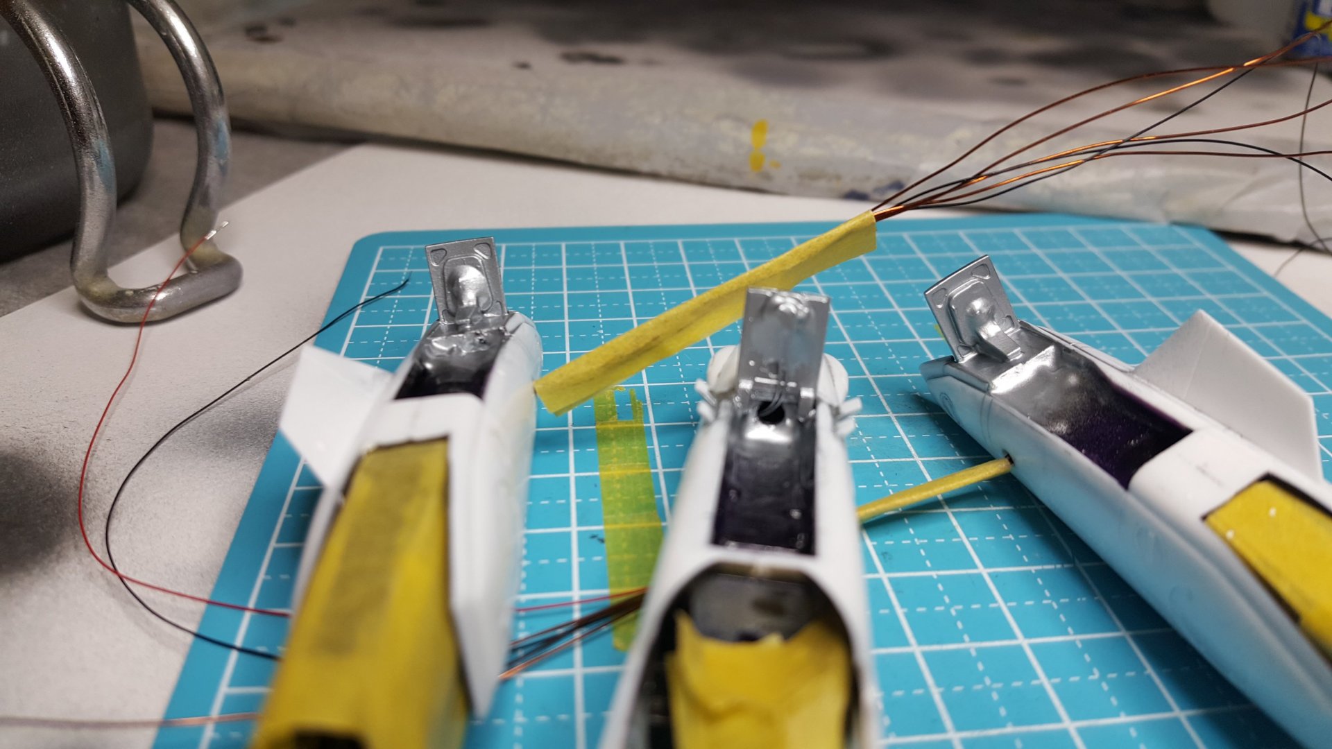
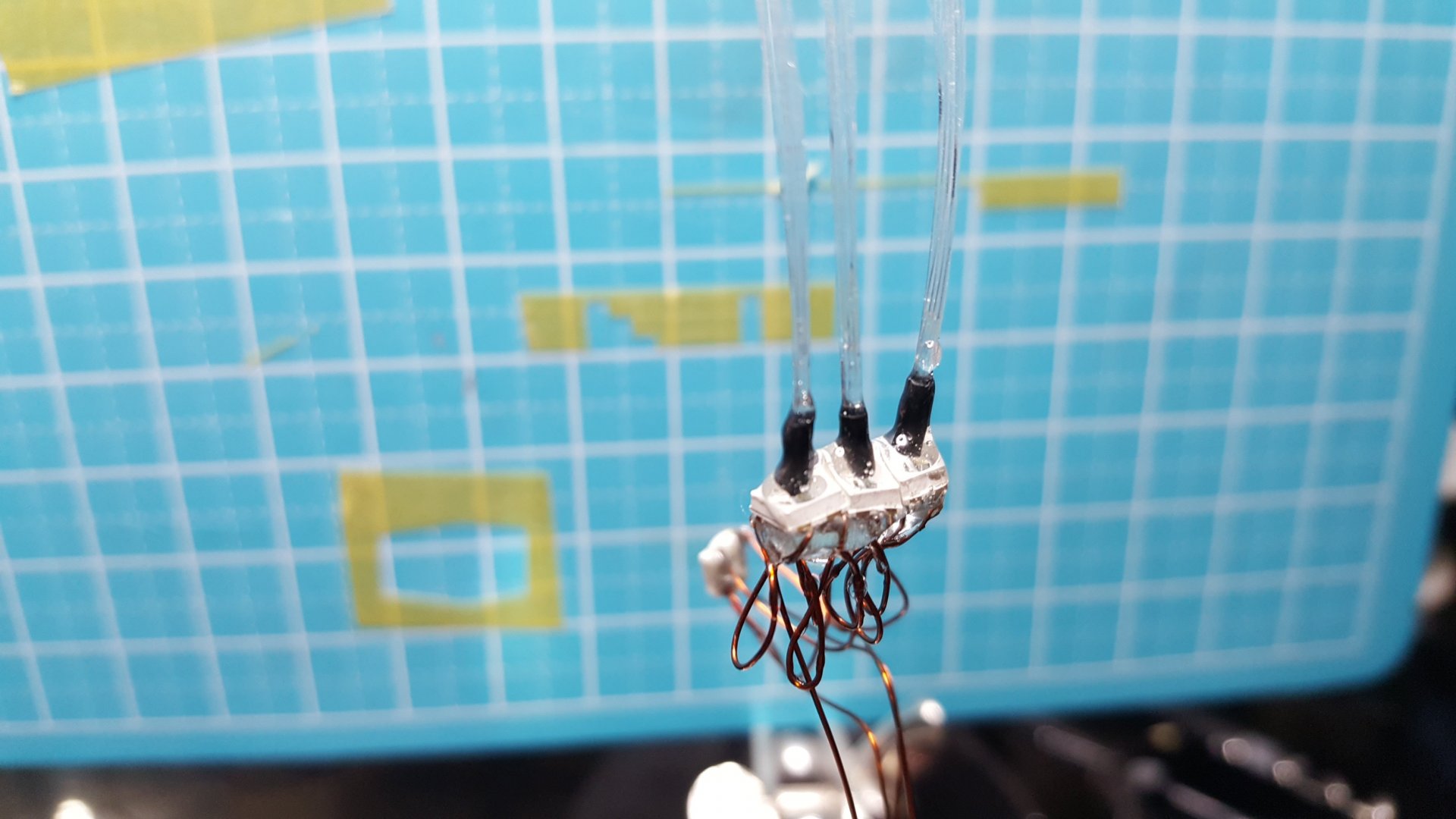
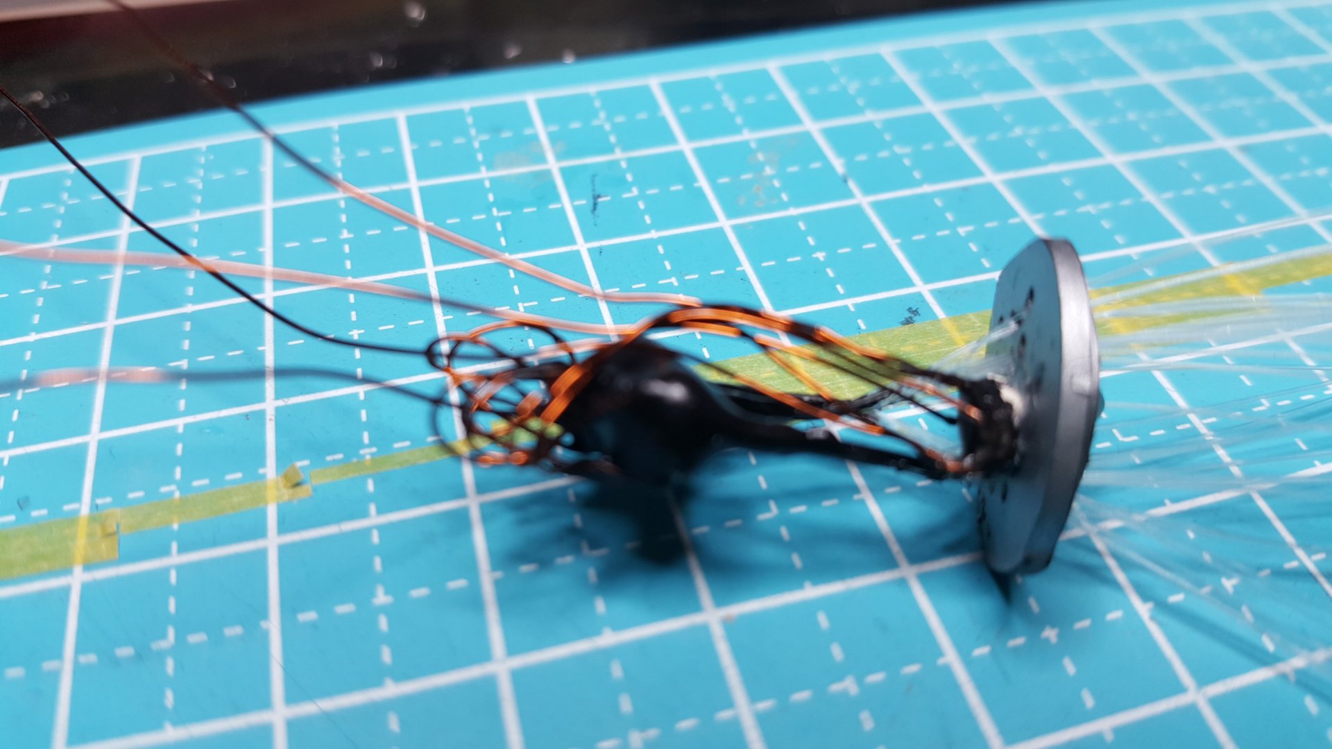
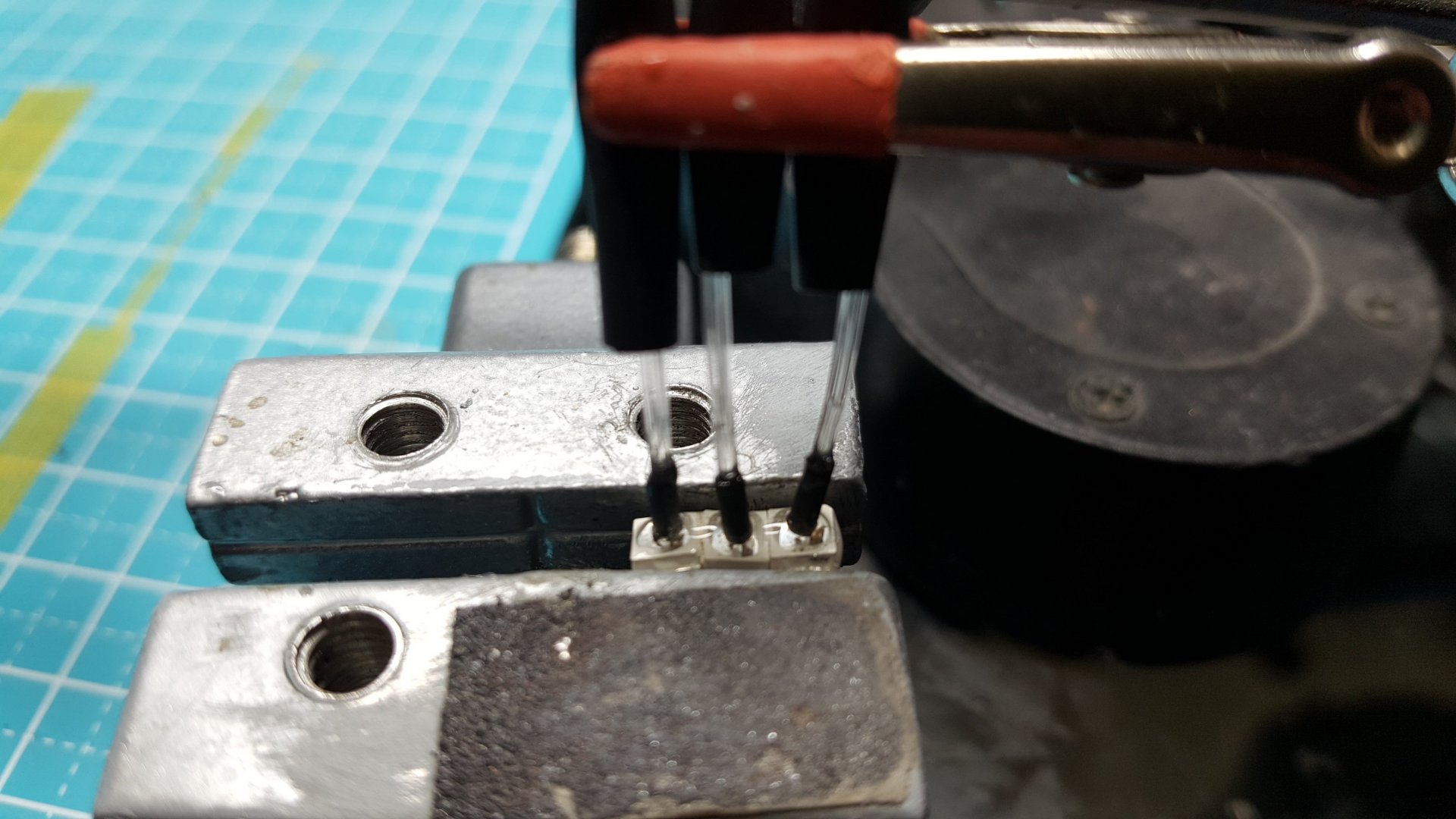
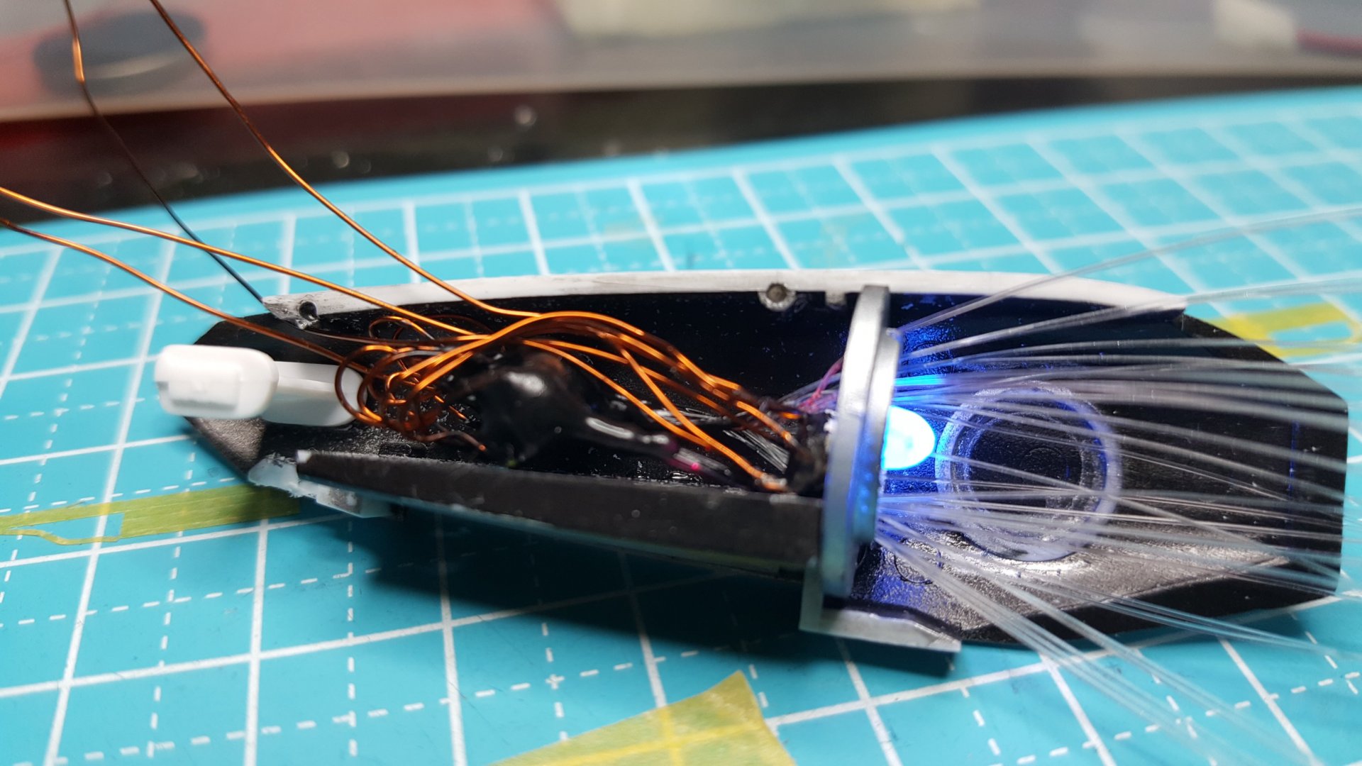
To light the engines, I used 4x 3535 smd neopixels for each engine. They are the smallest I could find measuring 3.5mm. Three of the neopixels are attached to 10x 0.25mm plastic optical fibers each. The fourth neopixel is for the main engine. I use a table vice and magnifying glass for soldering work, then I use 5 min epoxy for linking the smds together and to connect the fiber with some shrink tubing, a little trick I learned from NZEOD. I light block the neopixels with some polyeurethane primer so that the light only comes out the fiber and the main engine. All the 4 neopixels are controlled by one pair of wires led out of the completed leg part (neopixels actually have 3 wires each, unlike normal leds with a pair of wires). Part of the idea is to minimize the number of wires. To fit the wiring I also use the thinnest wires I can, such as 0.25 or 0.30mm enamel (magnet) wires. I use the clear parts again for the main engine to diffuse the 4th led, and I light block most of the part with black primer and metalic paint. I also drill some holes in the part to lead out the 30x strands of fiber. I blink the 4 separate leds at different colors and speed untill I get the effect I want. I then trim the fiber to the edge of the engines. I got this idea from an awesome Yamato Gun Gauge build. At the end of my above video you can also see that I use a bit of clear pla plate sanded down to diffuse the main engine led.
- 137 replies
-
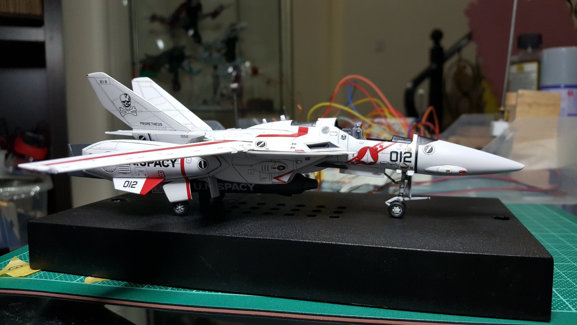
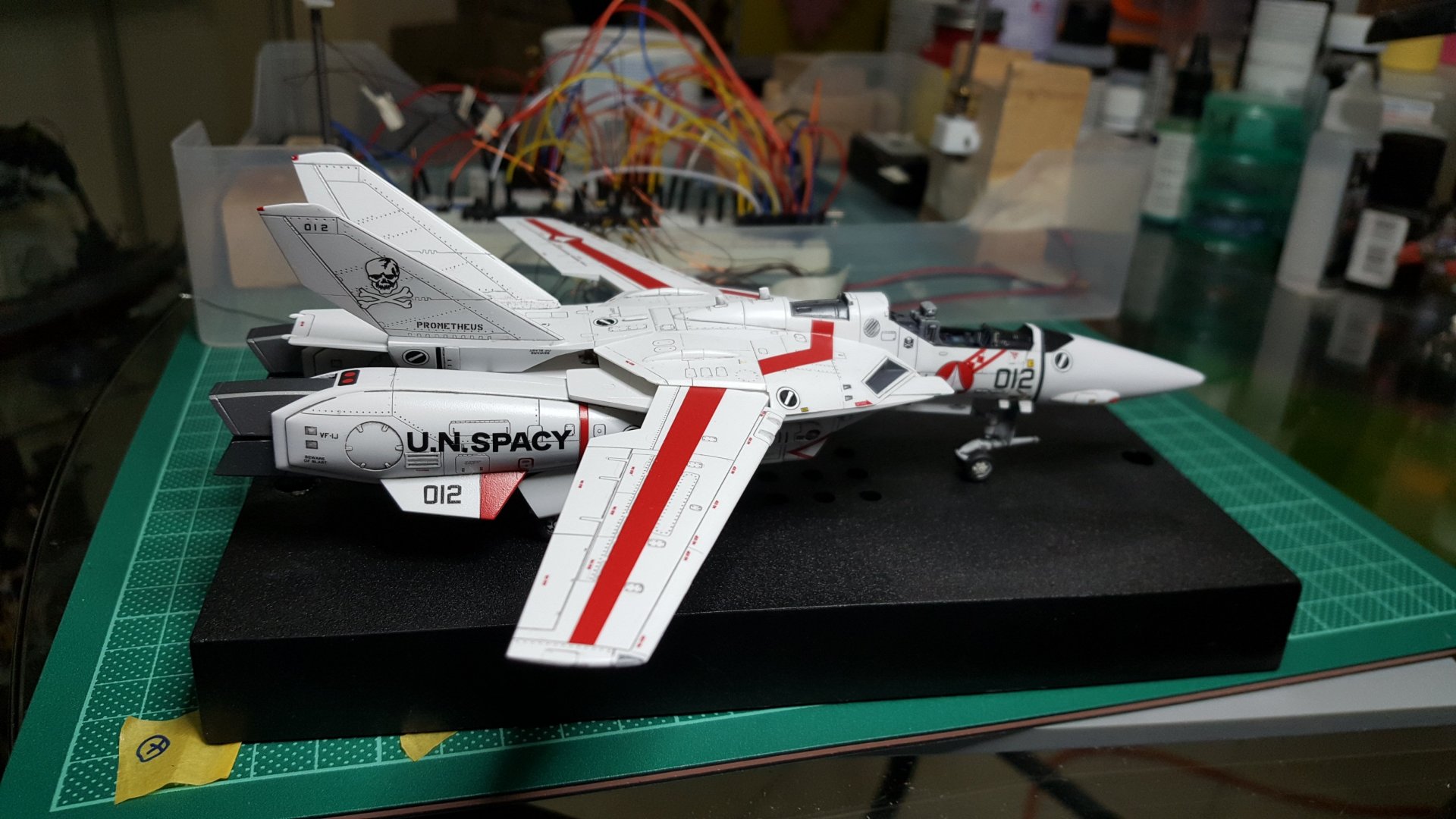
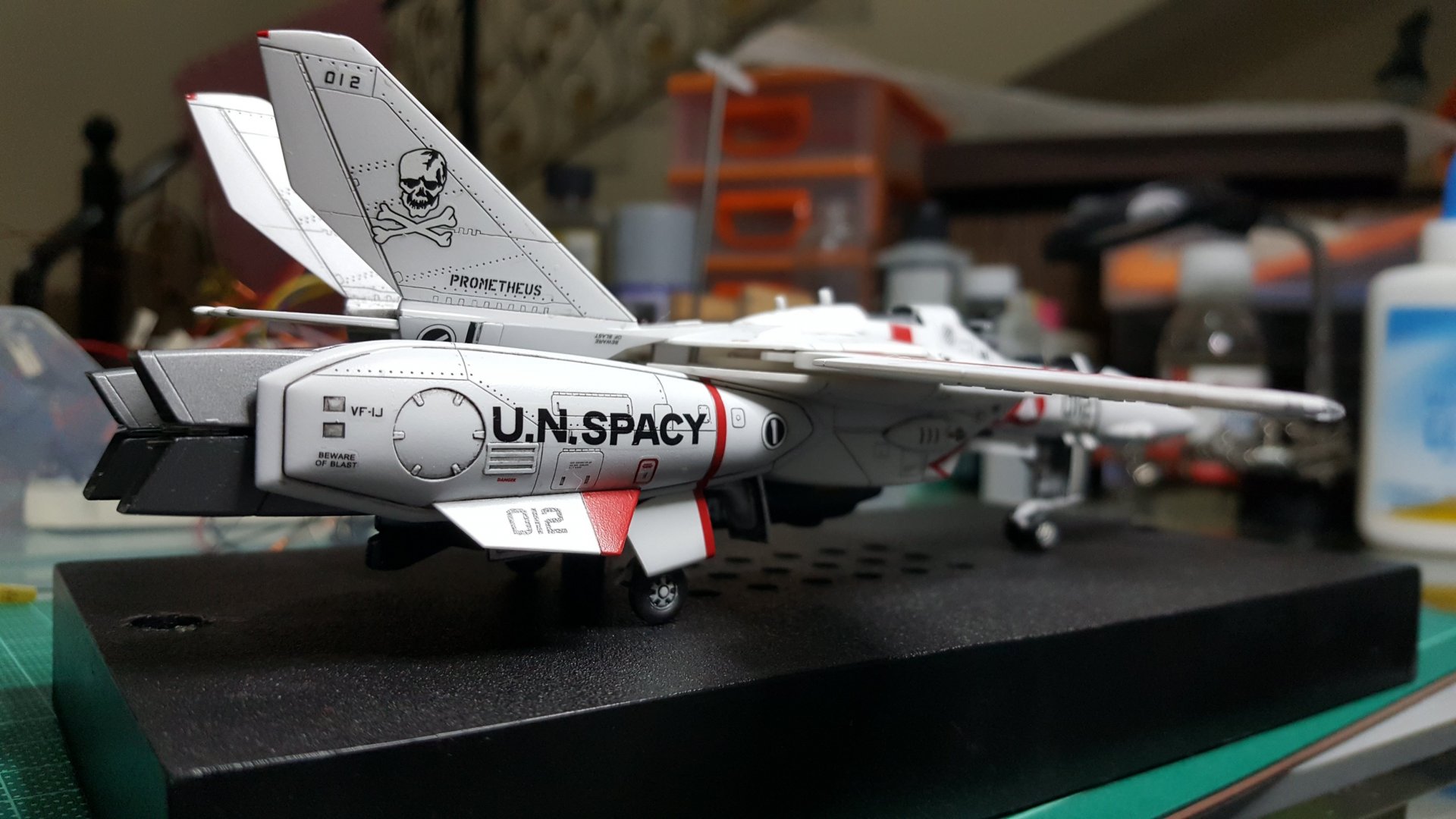
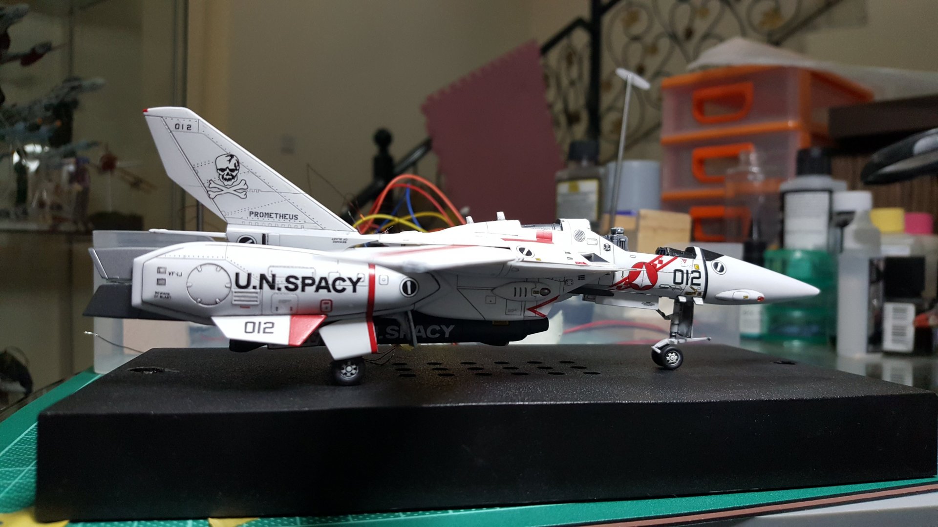
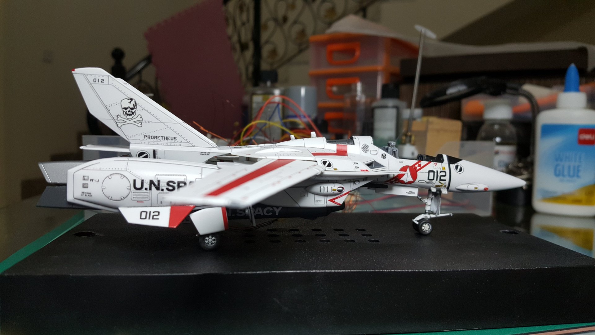
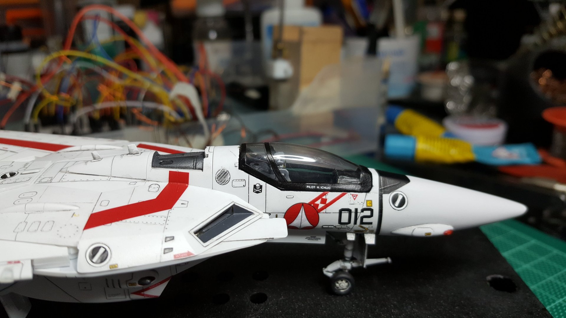
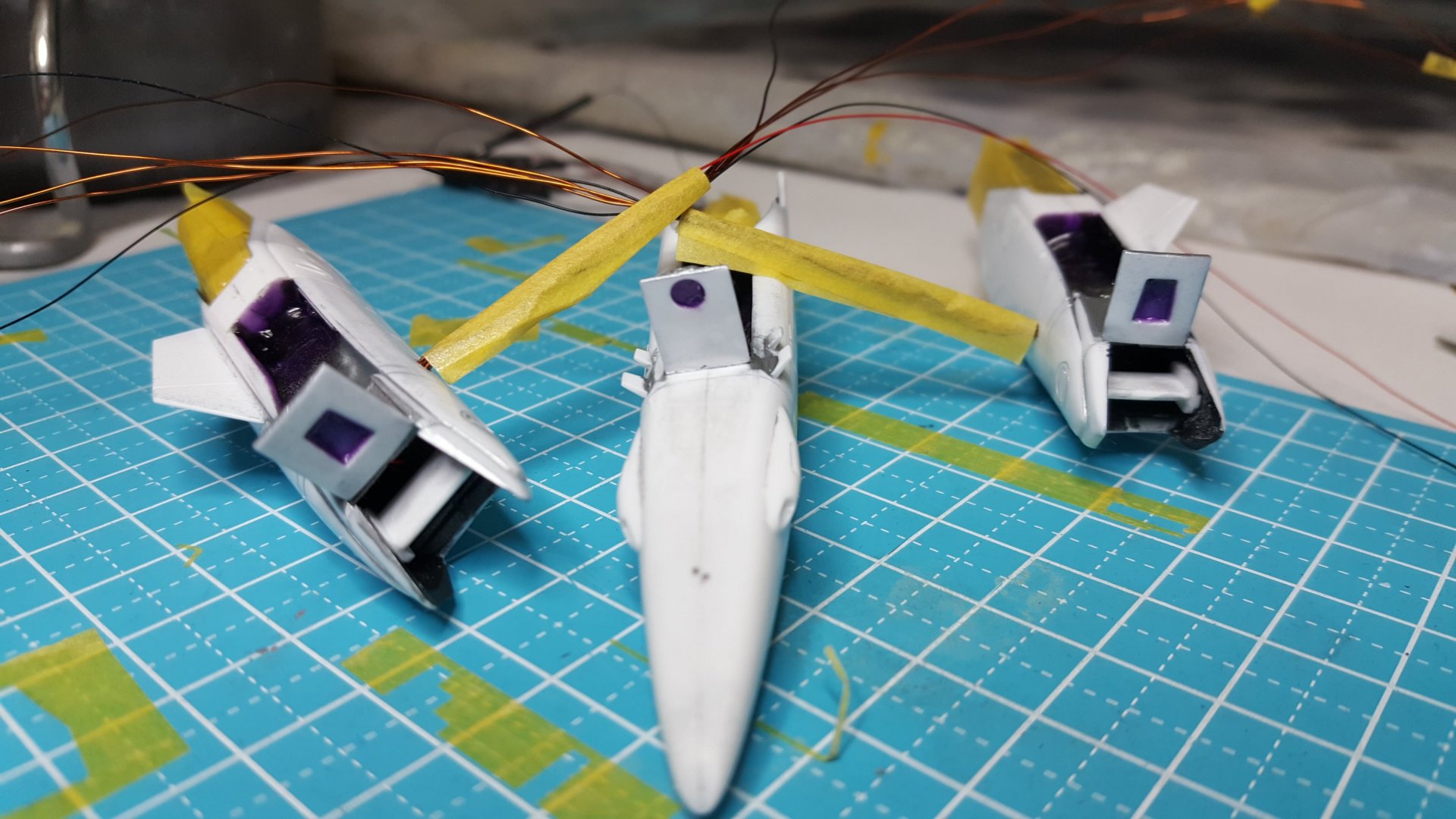
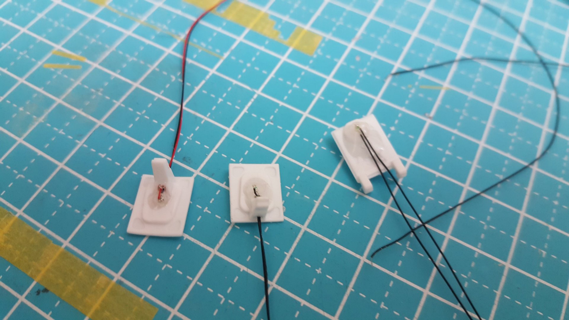
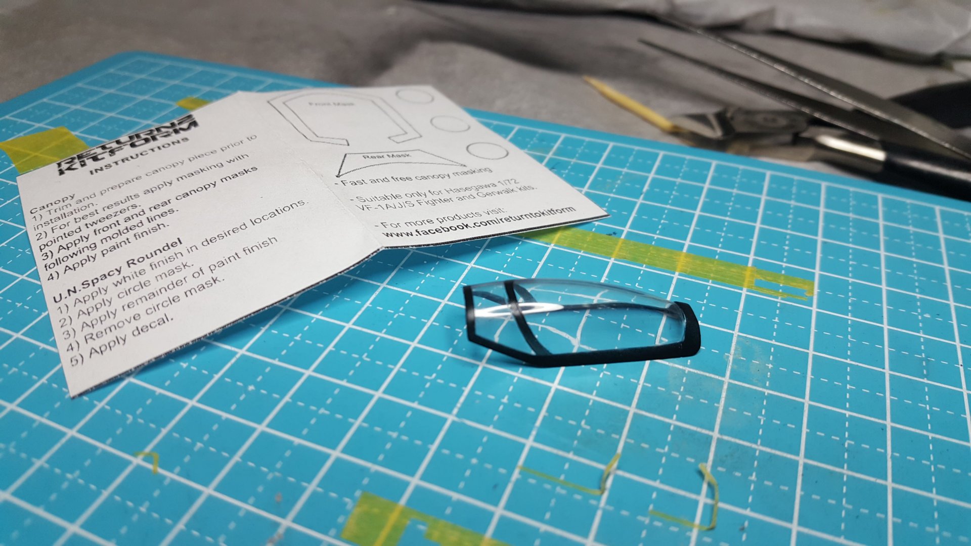
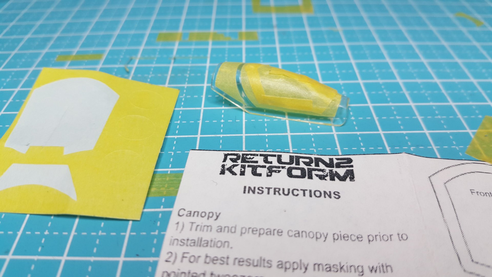
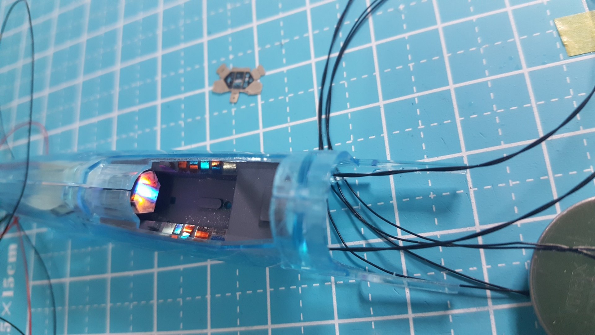
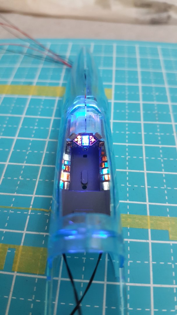
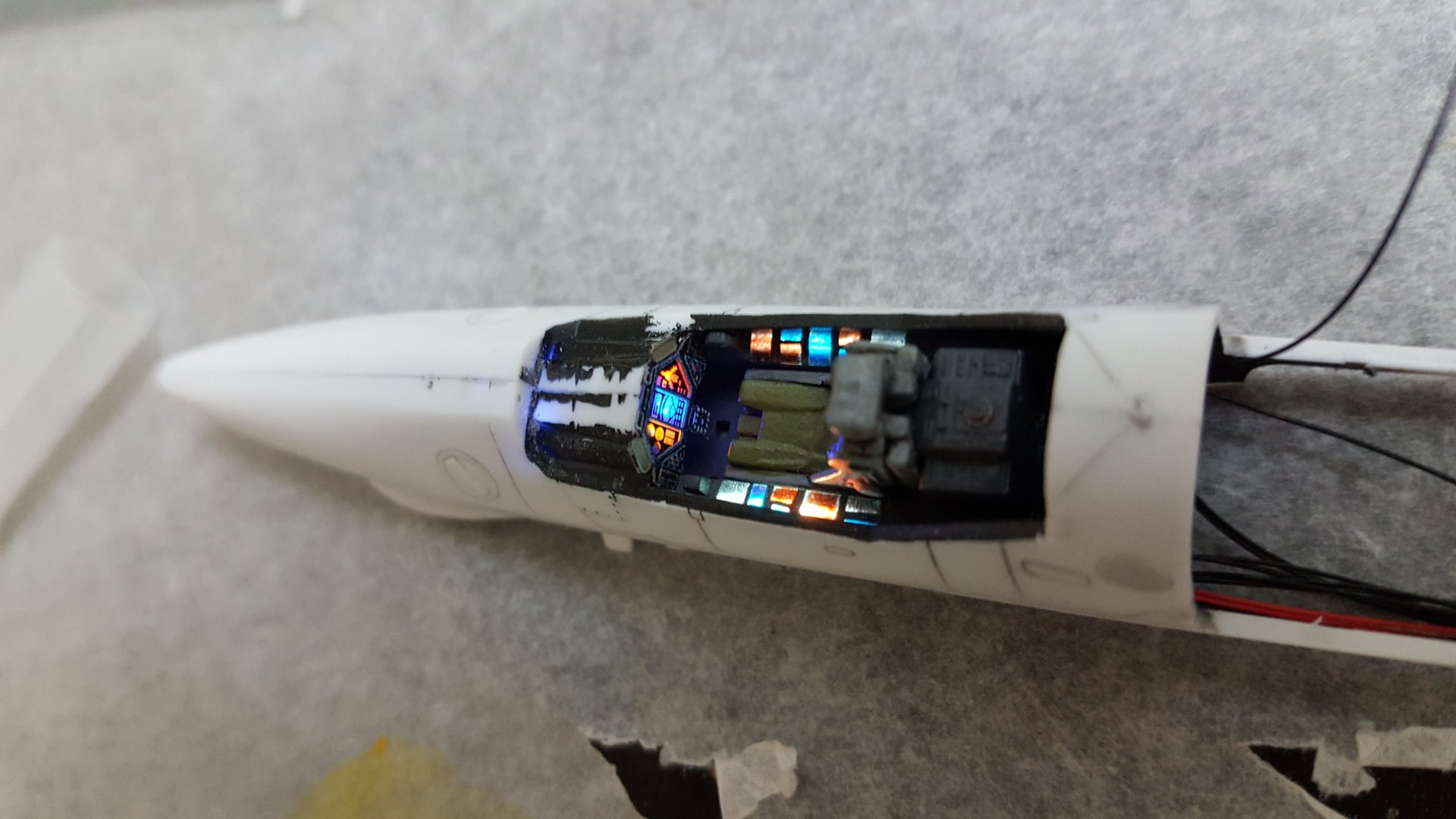
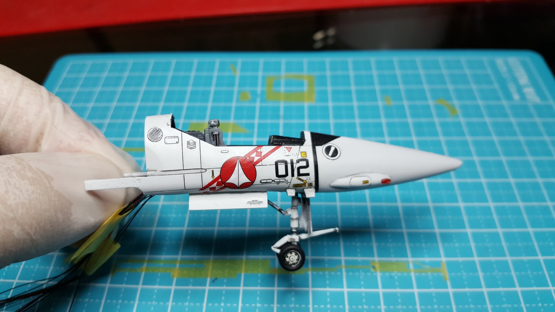
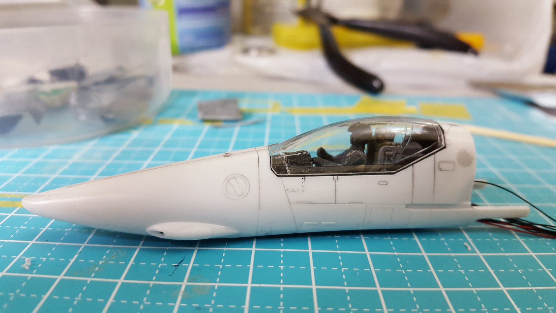
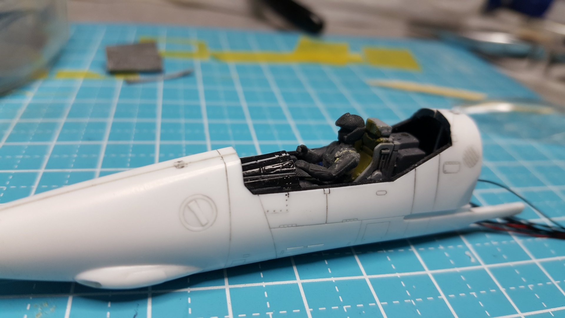
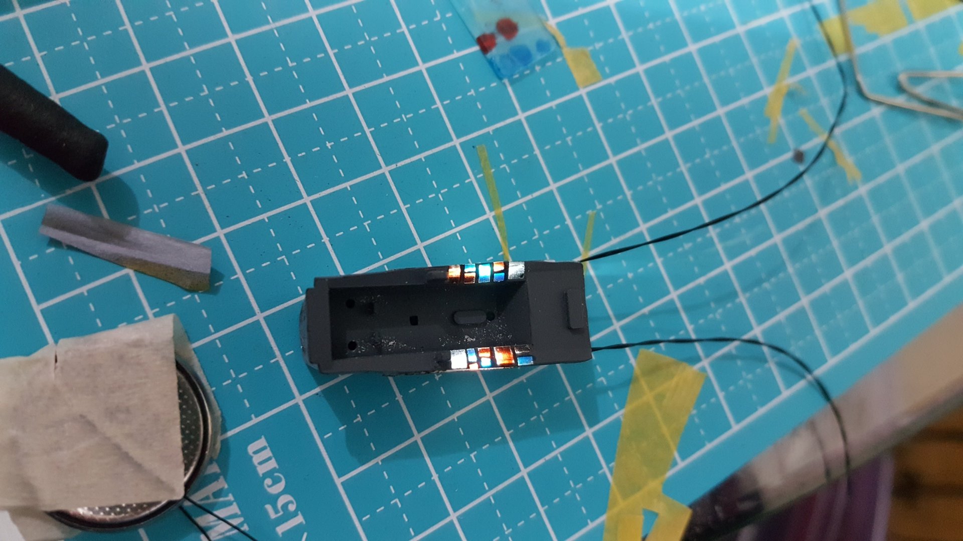
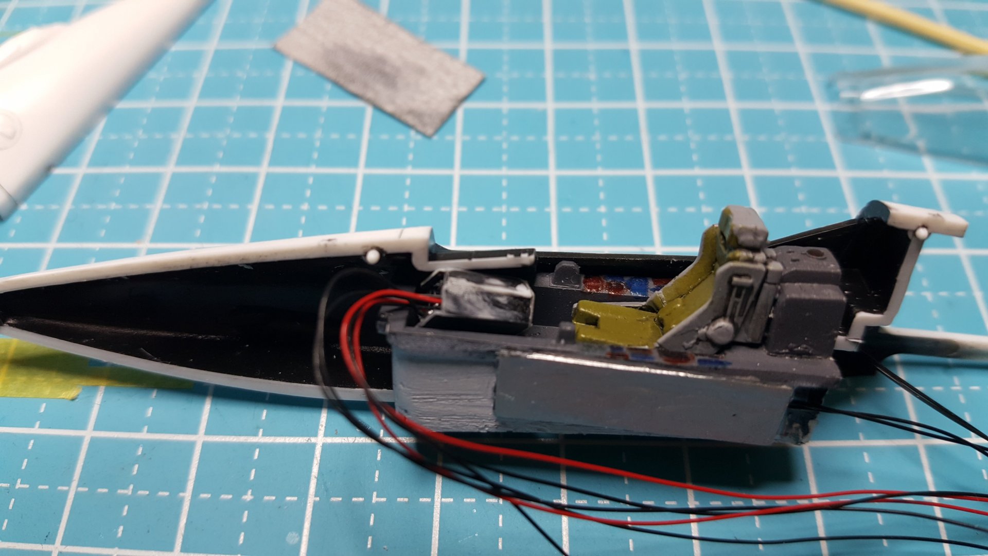
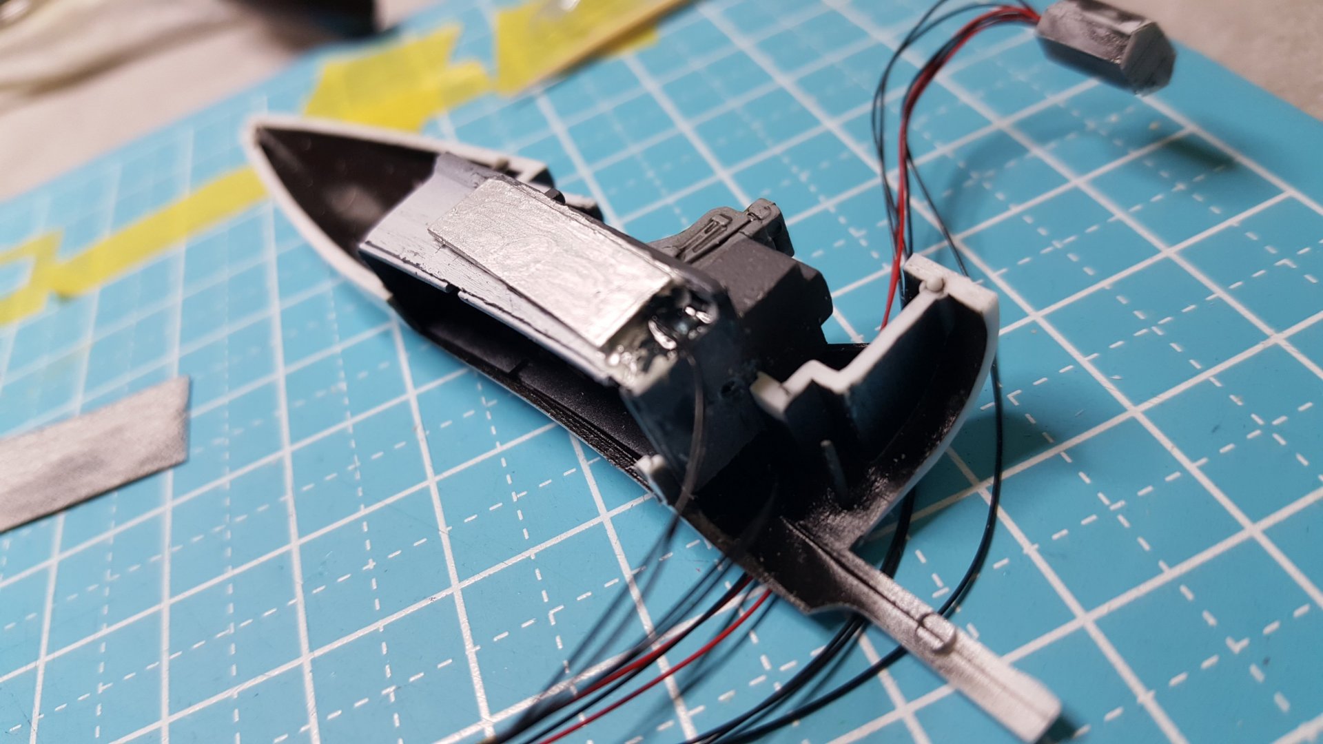
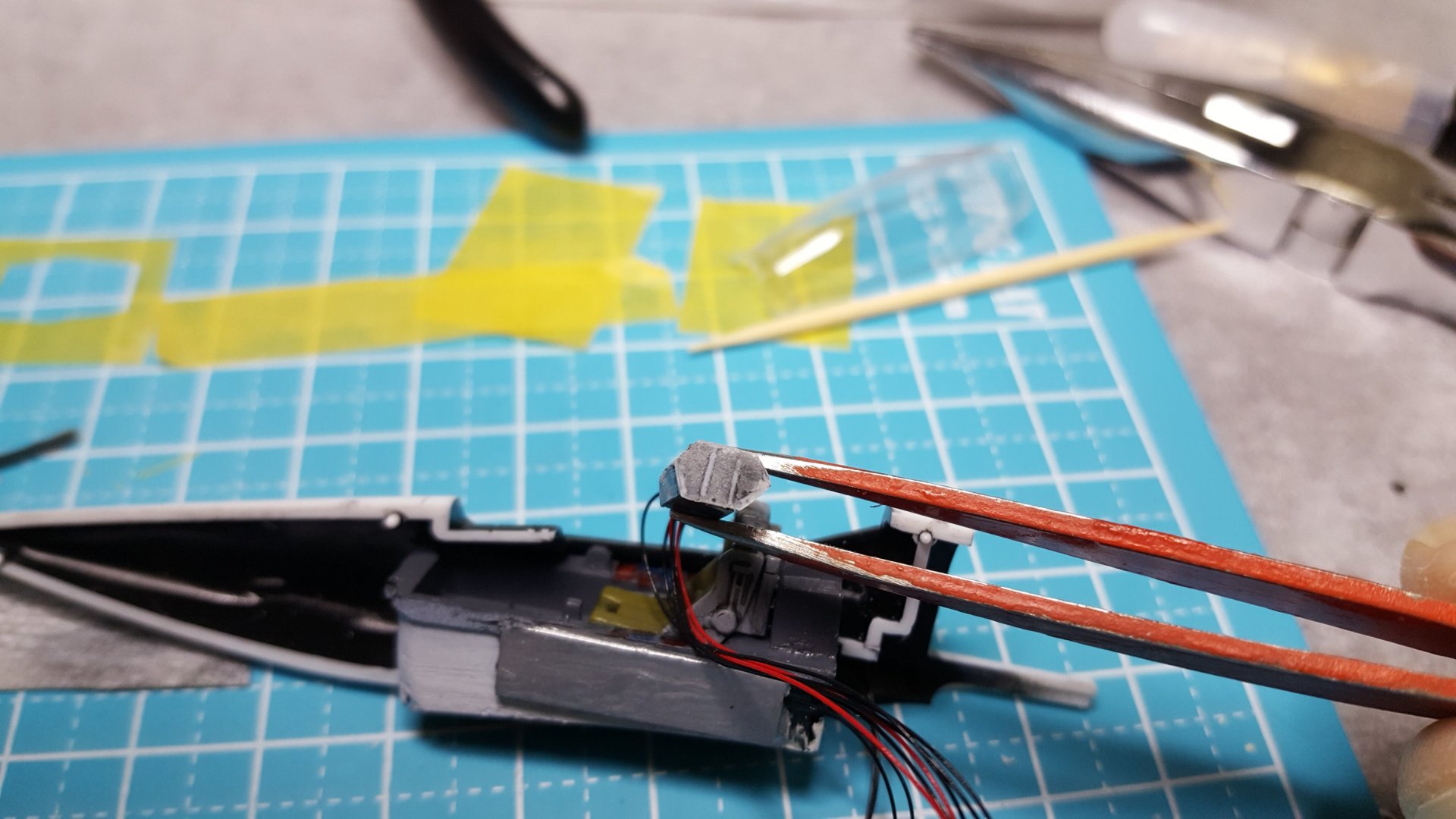
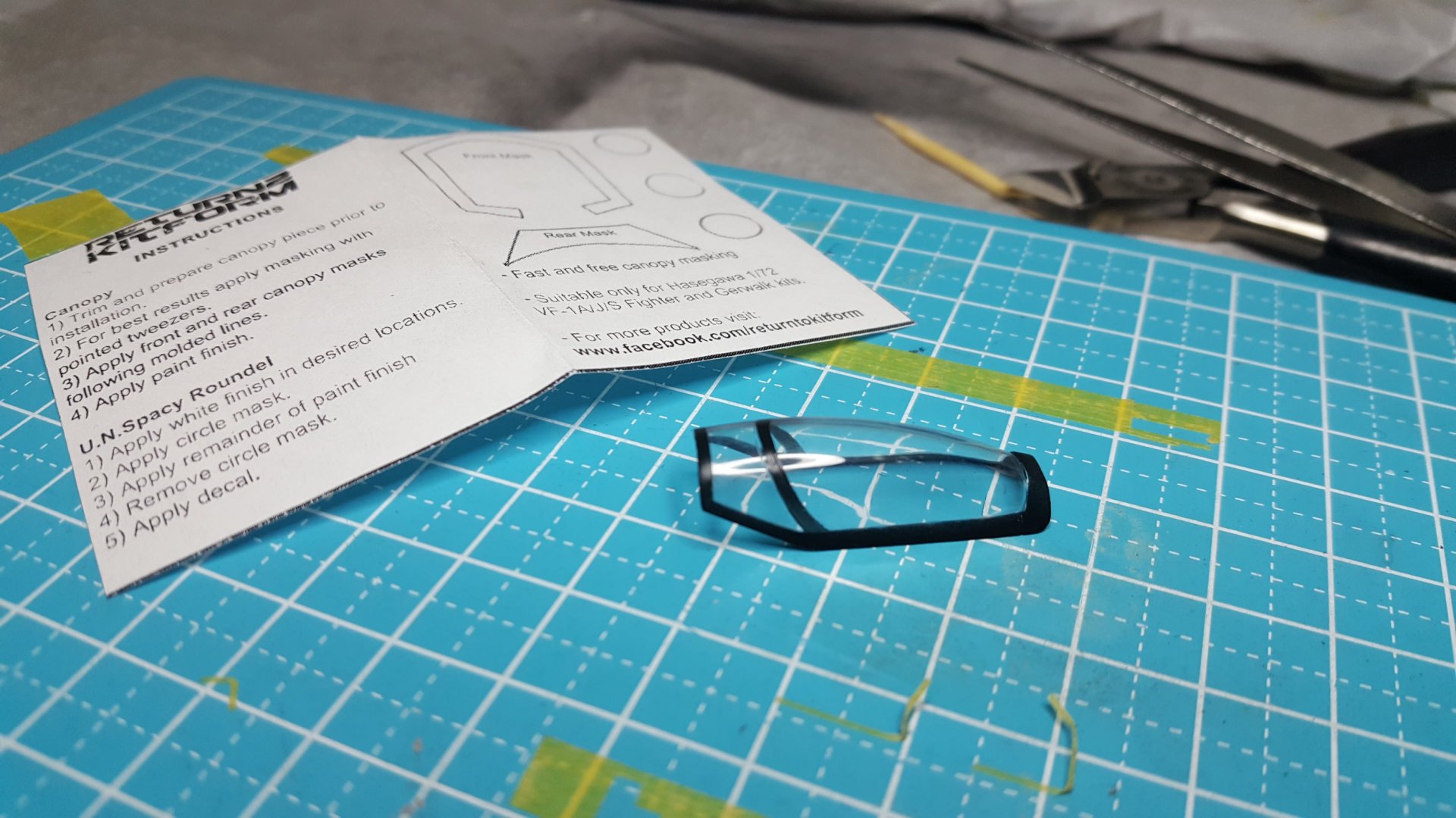
Up first is the cockpit WIP: I used the Hasegawa "Clear Version" Valk kit for the cockpit lighting. I masked off little squares for the side panels, then primed in black and painted many coats for light blocking. I then hand painted the panels in various clear tamiya colors. (Next time I would clear paint BEFORE masking and priming to get a cleaner finish). To get the side panels lit up I used a dremel to shave the sides of the canopy and used a strip of pla plate to create a little light box, which are light blocked with black and metallic paints. I find metallic steel to do a good job of light blocking. The leds are 0402 smds, less than 0.5mm width with a resistor for each led. For the cockpit panel lighting I scratched by hand a tiny little console with three panels sized to the Jasmin Models photo etch. You can see above the three panels and a clear pla plate sanded down to diffuse the light. Above is a test fitting before installing the photo etch and screens. All 5 pairs of wires are sent out the back and into the valk body to conceal them (6 pairs once I added the landing lights). Above I have installed the screen with panel details that comes with the Jasmin/Dream Model photo etch. At this stage they were perfect, but they are really easy to smudge in all the upcoming steps, and I managed to screw them up a bit in the end. But not a complete disaster. Above is the final installation of all photo etch parts and sealing/sanding of the cockpit to hide the seam lines. I ditch the Clear Valk from here on out, and start using only the normal kit, because painting a clear kit with lighting is a bad idea. (Still no smudges to screw up my cockpit panel. That comes later...) This is a shapeways 1/72 pilot. Had to chop his butt off to fit in there. What do you guys/gals think of the scale? Seems big to me, but I'm gonna go with it. I used RTK's amazing 1/72 masks for a clean finish. Highly recommended to avoid a nasty cockpit. Final paint and F-14 Diamondback decals. Worst decals I've ever used... had to lay each diamond decal down individually by hand, because the suckers disintegrated on me, but I'm not a perfectionist... Also wish I had painted the white circle decal screens rather than use the white decals provided by Hasegawa, before using the UN Spacy kite decal. As it is, I made a mess of it with three layers of decals. I'm not a good painter and no one should take advice from me, but this was my process: Mix white and gray lacquer Mr. Hobby airbrush surfacer primer. I use a mix because a gray primer will require a million coats of white base coat, so this makes it faster. Base coat is tamiya white with 5% gray of any sort. Then air brush gloss clear coat with Mr. Hobby Levelling thinner, before tamiya panel line wash. I also mix the panel line wash 50-50 gray and black so its not too dark. Then closed up with a satin clear coat. I code a simple sequence in arduino with a fade up and down. This is simpe stuff, anyone can learn it. These 3 tutorials got me started from nothing. I am not a tech or electronics guy in any way what so ever. https://learn.adafruit.com/lets-put-leds-in-things/from-scratch https://learn.adafruit.com/all-about-leds/overview https://learn.adafruit.com/adafruit-neopixel-uberguide/basic-connections
- 137 replies
-
Thanks guys. Glad you like it. Still lots more to do to get it on the Prometheus
- 137 replies
-
I've pinned the final build video up top, followed by the WIP in the rest of the thread. This is a new build to continue my motorized Ranger squadron, but this time I am using Xigfrid's Shapeways 3D printed gear. With Xigfrid's gear I got a much smoother operation, and in many ways an easier installation, although I can't say its ever that easy to cut into your valk like this. I also learned from my last build for the Motorized 1/72 VF-1S Launch Arm to pay closer attention to the type and speed of the motor as well as the coding to test full performance before final installation. In the last build I ended up with a slower motor speed than I expected. I also wanted to give a better step-by-step WIP with Xigfrid's gear, which will be coming up.
- 137 replies
-
- 4
-

-

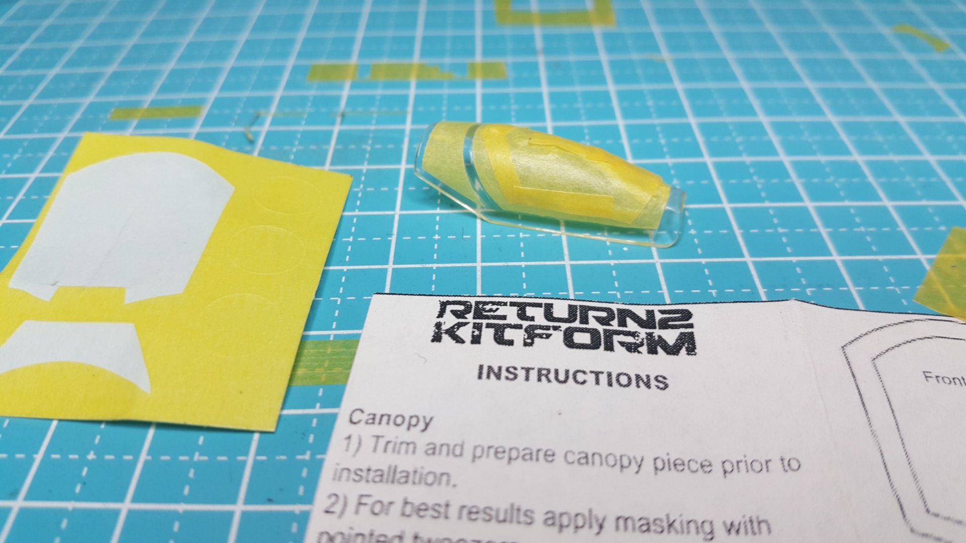
Valkyrie Canopy Masks - 1/48 TV VF-1 and 1/72 VF-1D set available!
arbit replied to Return To Kit Form's topic in Model kits
I highly recommend these. Got the cleanest finish ever on my 1/72 VF-1. No nightmare of cutting my own mask and scratching the canopy, no finger smuges from repeated handing, no problems at all.- 63 replies
-
- valkyrie
- vf-1 valkyrie
-
(and 2 more)
Tagged with:
-
Whoa! What a beast!
-

Bolt’s Blt comp entry#1 Neo Grade VF1 Armored Valkyrie
arbit replied to Bolt's topic in The Workshop!
We need these competitions more often! Never saw so many Macross resin builds at one time. Awesome -
And where will you store this...

